January 2016
2-34
WorkCentre WorkCentre 4150/4250/4260WorkCentre 4150/4250/42604150/
05-600
Status Indicator RAPs
05-600 DADF Jam 6 RAP
05-600 The machine has detected that a DADF sensor is actuated when the machine is
switched on.
Procedure
WARNING
Switch off the electricity to the machine. Disconnect the power cord from the customer
supply while performing tasks that do not need electricity. Electricity can cause death or
injury. Moving parts can cause injury.
Go to the relevant procedure:
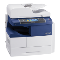
• 4150 Checkout
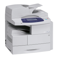
• 4250/4260 Checkout
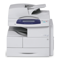
• 4265 Checkout
4150 Checkout
Refer to Wiring Diagram 11. Perform the following:
1. Open the DADF top cover assembly, PL 5.15 Item 11. Remove all jammed paper.
2. Raise the DADF input tray, PL 5.10 Item 5. Remove all jammed paper.
3. Check the document path for damage or obstructions.
4. Check that the following actuators move freely and are not damaged:
• Document detect sensor actuator, PL 5.20 Item 17.
• Paper width sensor actuator, PL 5.20 Item 17.
• Paper length sensor actuator, PL 5.10 Item 14.
• Registration sensor actuator, PL 5.15 Item 12.
• Scan sensor actuator, PL 5.25 Item 28.
• Gate sensor actuator, PL 5.10 Item 26.
• Duplex sensor actuator, PL 5.25 Item 27.
5. Enter dC330. Check the following sensors. Install new components as necessary:
• Code 05-100, document detect sensor (Q05-100), PL 5.20 Item 13.
• Code 05-110, paper width sensor (Q05-110), PL 5.20 Item 13.
• Code 05-120, paper length sensor (Q05-120), PL 5.10 Item 12.
• Code 05-130, registration sensor (Q05-130), PL 5.15 Item 14.
• Code 05-140, scan sensor (Q05-140).
• Code 05-150, gate sensor (Q05-150), PL 5.10 Item 24.
• Code 05-170, duplex sensor (Q05-170).
NOTE: The scan sensor and duplex sensor are mounted on the DADF PWB, PL
5.20 Item 6.
6. Check the following wiring:
• Between the document detect sensor, and CN4 on the DADF Sensor PWB.
• Between the paper width sensor and CN4 on the DADF Sensor PWB.
• Between the paper length sensor and CN3 on the DADF Sensor PWB.
• Between the registration sensor and CN5 on the DADF Sensor PWB.
• Between the gate sensor and CN2 on the DADF Sensor PWB.
• Between CN1 on the DADF Sensor PWB and CN3 on the DADF PWB.
7. If necessary, install new components:
• DADF PWB, PL 5.20 Item 6.
• DADF sensor PWB, PL 5.20 Item 4.
• Document transport assembly, PL 5.10 Item 2.
4250/4260 Checkout
Refer to Wiring Diagram 29. Perform the following:
1. Open the DADF top cover assembly, PL 5.30 Item 2. Remove all jammed paper.
2. Raise the DADF input tray, PL 5.30 Item 11. Remove all jammed paper.
3. Check the document path for damage or obstructions.
4. Check that the following actuators move freely and are not damaged:
• Document detect sensor actuator, PL 5.45 Item 15.
• Paper width sensor actuator, PL 5.45 Item 15.
• Paper length sensor actuator, PL 5.32 Item 10.
• Registration sensor actuator, PL 5.40 Item 18.
• Scan sensor actuator, PL 5.55 Item 4.
• Gate sensor actuator, PL 5.55 Item 3.
• Duplex sensor actuator, PL 5.55 Item 5.
• R stack sensor actuator, PL 5.35 Item 17.
5. Enter dC330. Check the following sensors. Install new components as necessary:
• Code 05-100, document detect sensor (Q05-100), PL 5.45 Item 10.
• Code 05-110, paper width sensor (Q05-110), PL 5.45 Item 10.
• Code 05-120, paper length sensor (Q05-120), PL 5.32 Item 9.
• Code 05-130, registration sensor (Q05-130), PL 5.40 Item 17.
• Code 05-140, scan sensor (Q05-140), PL 5.55 Item 1.
• Code 05-150, gate sensor (Q05-150), PL 5.55 Item 1.
• Code 05-170, duplex sensor (Q05-170), PL 5.55 Item 1.
• Gate HP sensor, PL 5.50 Item 20.
• R stack sensor, PL 5.35 Item 16.
NOTE: There is not a component control code for the gate HP sensor or R stack
sensor.
6. Check the following wiring:
• Between the document detect sensor, and CN3 on the DADF PWB.
• Between the paper width sensor and CN3 on the DADF PWB.
• Between the paper length sensor and CN5 on the DADF PWB.
• Between the registration sensor and CN7 on the DADF PWB.
• Between the scan sensor and CN10 on the DADF PWB.
• Between the gate sensor and CN10 on the DADF PWB.
• Between the duplex sensor and CN10 on the DADF PWB.
• Between the gate HP sensor and CN9 on the DADF PWB.
• Between the R stack sensor and CN12 on the DADF PWB.
7. If necessary, install new components:
• DADF PWB, PL 5.30 Item 24.
 Loading...


