January 2016
4-69
WorkCentre 4150/4250/4260WorkCentre WorkCentre 4150/4250/42604150/
REP 5.18
Repairs and Adjustments
CAUTION
In the following activity, ensure that only the three brass mounting screws are removed from
the Exit Guide Cover.
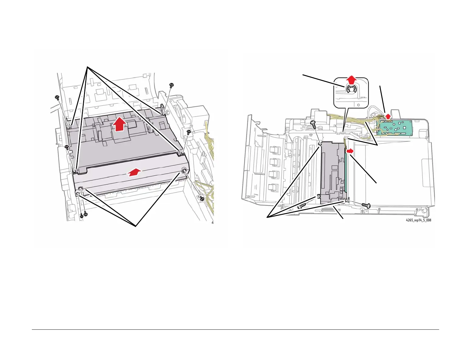
10. Remove the Pickup Guide Assembly and the Exit Guide Cover (Figure 8).
Figure 8 Removing the Pickup Guide Assembly and Exit Guide Cover
11. Prepare to remove the CCD (Figure 9).
NOTE: Earlier configurations of the 4265 may have a small plastic cover mounted over
the outboard side of the CCD, directly above the spring. If present, it is removed by
removing the three mounting screws.
Figure 9 Preparing to Remove the CCD
2
Remove the three brass mounting
screws from the Exit Guide Cover.
3
Remove the two components
from the machine.
1
Remove the four mounting screws from the Pickup Guide Assembly.
1
Remove the e-clip.
2
Disconnect CN8 on the
DADF PWB.
3
Route the CN8 wire
bundle out of the two
wire clips, and
through the plastic
rings on the CCD.
4
Disconnect the connector.
6
Remove the three mount-
ing screws.
5
Disconnect the spring attached to
the underside of the CCD.

 Loading...


