Spartan-6 FPGA PCB Design and Pin Planning www.xilinx.com 29
UG393 (v1.1) April 29, 2010
Basic PDS Principles
F
RSELF
= 53 MHz (capacitor data sheet parameter)
L
MOUNT
= 0.8 nH (based on PCB mounting geometry)
To determine the effective in-system parasitic inductance (L
IS
), add the via parasitics:
L
IS
=L
SELF
+L
MOUNT
=0.9nH+0.8nH
L
IS
= 1.7 nH Equation 2-3
The values from the example are used to determine the mounted capacitor resonant
frequency (F
RIS
). Using Equation 2-1:
Equation 2-4
Equation 2-5
F
RSELF
is 53 MHz, but F
RIS
is lower at 38 MHz. The addition of mounting inductances
shifts the effective-frequency band down.
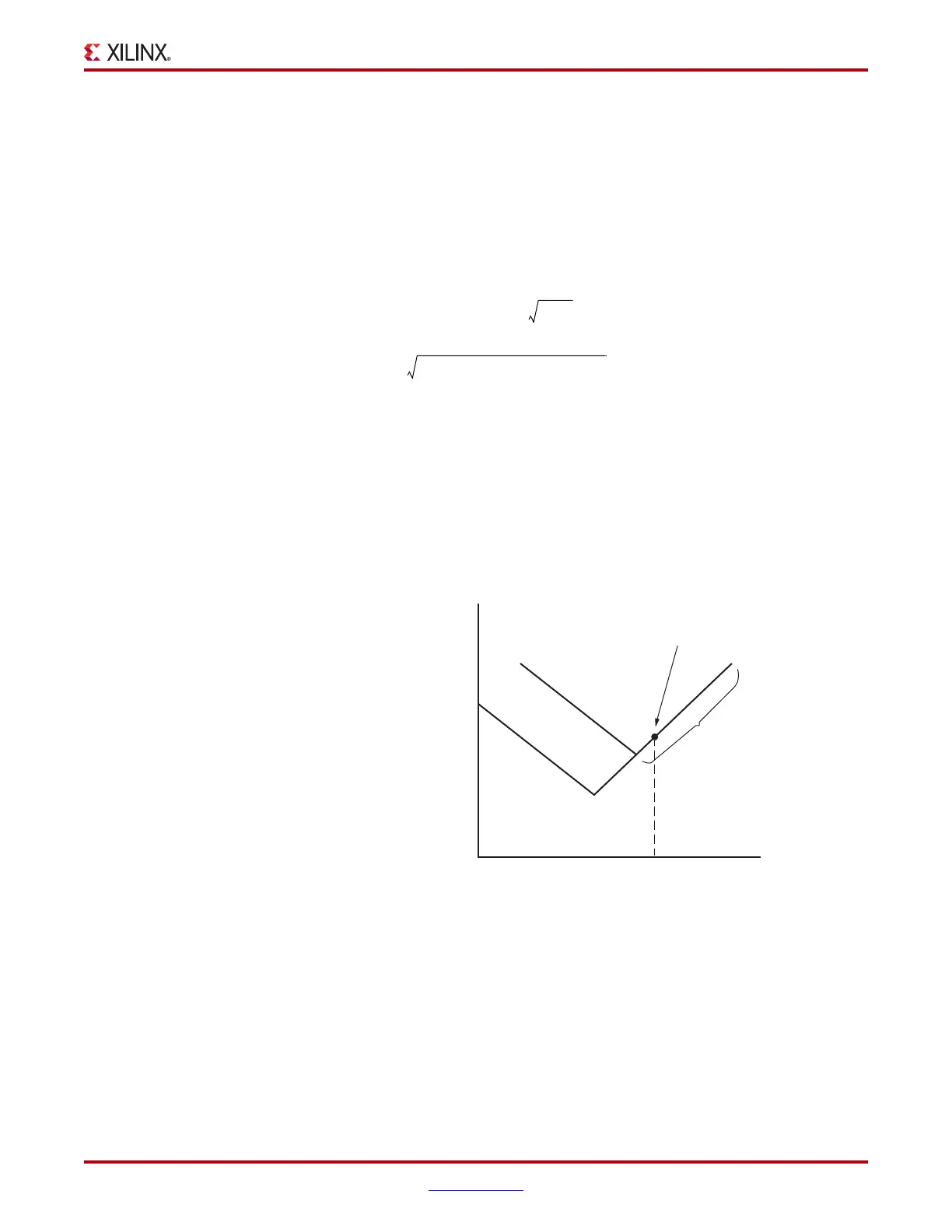
A decoupling capacitor is most effective at the narrow-frequency band around its resonant
frequency, and thus, the resonant frequency must be reviewed when choosing a capacitor
collection to build up a decoupling network. This being said, capacitors can be effective at
frequencies considerably higher and lower than their resonant frequency. Recall that
capacitors of differing values in the same package share the same inductance curve. As
shown in Figure 2-8, for any given frequency along the inductive portion of the curve, the
capacitors are equally effective.
X-Ref Target - Figure 2-8
Figure 2-8: Effective Frequency Example
F
RIS
1
2π L
IS
C
-------------------------=
F
RIS
1
2π 1.7
9–
×10 H()0.01
6–
×10 F()⋅
------------------------------------------------------------------------------------
38
6
×10 Hz==
Inductance (Z)
Frequency
ug393_c2_08_091809
F
2
0805
0805
0.47 μF
4.7 μF
Inductive
Portion
Z Value at F
2
is Equal

 Loading...


