36 www.xilinx.com Spartan-6 FPGA PCB Design and Pin Planning
UG393 (v1.1) April 29, 2010
Chapter 2: Power Distribution System
Excessive noise at a certain frequency indicates a frequency where the PDS impedance is
too high for the device’s transient current demands. Using this information, the designer
can modify the PDS to accommodate the transient current at the specific frequency. This is
accomplished by either adding capacitors with effective frequencies close to the noise
frequency or otherwise lowering the PDS impedance at the critical frequency.
The noise spectrum measurement should be taken in the same manner as the peak-to-peak
noise measurement, directly underneath the device, or at a static I/O driven High or Low.
A spectrum analyzer takes its measurements using a 50Ω cable instead of an active probe.
• A good method attaches the measurement cable through a coaxial connector tapped
into the power and ground planes close to the device. This is not available in most
cases.
• Another method attaches the measurement cable at the lands of a decoupling
capacitor in the vicinity of the device that has been removed. The cable’s center
conductor and shield are soldered directly to the capacitor lands. Alternatively, a
probe station with 50Ω RF probes can be used to touch the decoupling capacitor
lands.
To protect the spectrum analyzer’s sensitive front-end circuitry, add a DC blocking
capacitor or attenuator in line. This isolates the spectrum analyzer from the device supply
voltage.
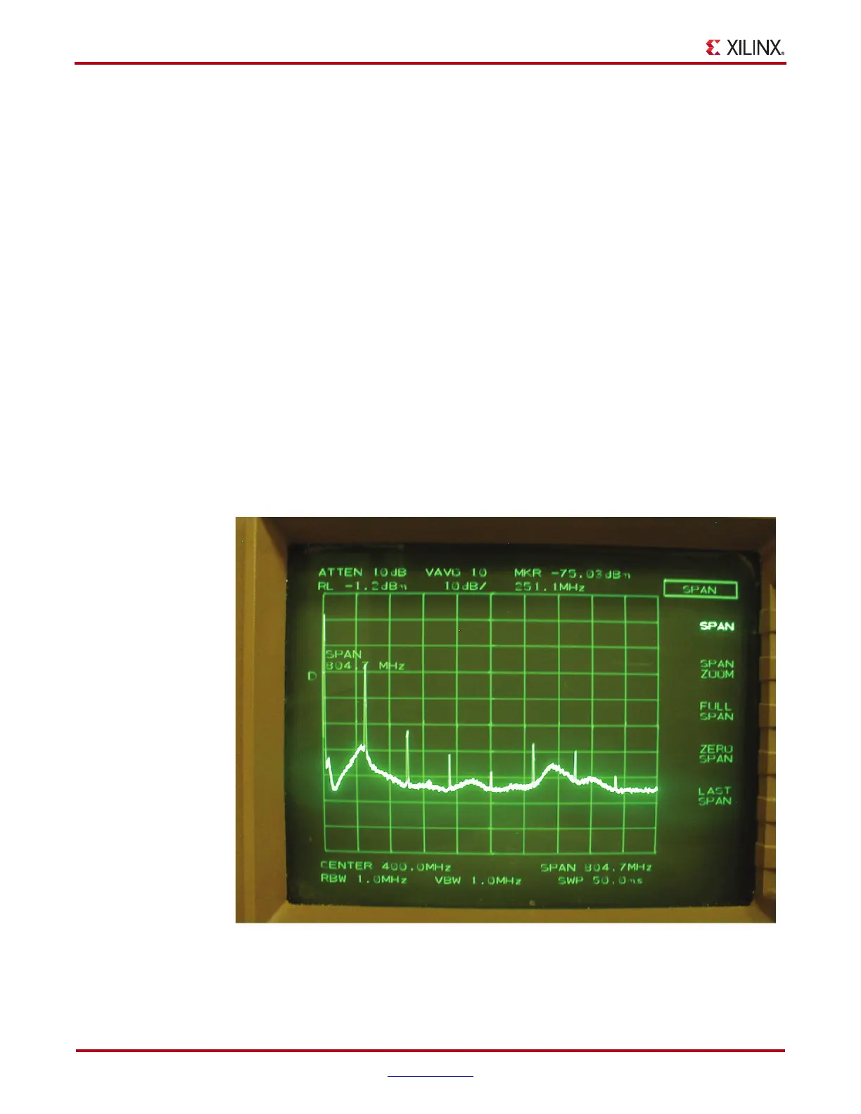
Figure 2-11 is an example of a noise spectrum measurement of the V
CCO
power-supply
noise, with multiple I/O sending patterns at 100 MHz.
X-Ref Target - Figure 2-11
Figure 2-11: Screenshot of Spectrum Analyzer Measurement of V
CCO

 Loading...


