6 / 99 www.xovis.com
2 Installation Fundamentals
Network requirements
The device needs to be connected to the network by a shielded Cat 5 RJ45 Cable. The plug
and the sensor need to be free from any mechanical pressure. The sensor supports Ethernet
10/100Mb Full/Half/Auto negotiation based on the IEEE 802.3 standard. It is highly
recommended to set the switch port to auto negotiation.
Power over Ethernet
The sensor is powered by PoE Class 0 compliant to IEEE 802.3af. As defined by the standard,
the network switch port needs to provide 15 Watts at 48 V.
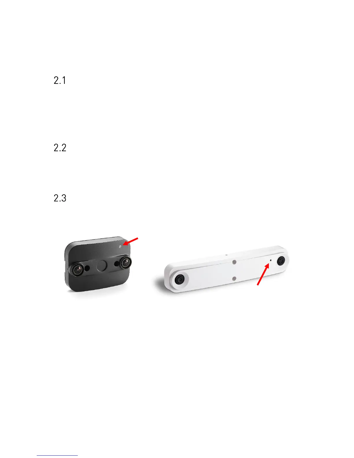
Sensor LED
The PC-Series sensor provides a multifunctional LED on the front side. The red arrow on the
next picture indicate the LED on the PC2 and PC3 models.
Figure 2: PC2 LED (left) and PC3 LED (right)
The LED indicates the following states:
- Green: Device is powered by PoE
- Orange/Green blinking: Device is up and running
The LED state can be useful during installation. When using the optional housing, the LED
will be covered after successful mounting.