95 / 99 www.xovis.com
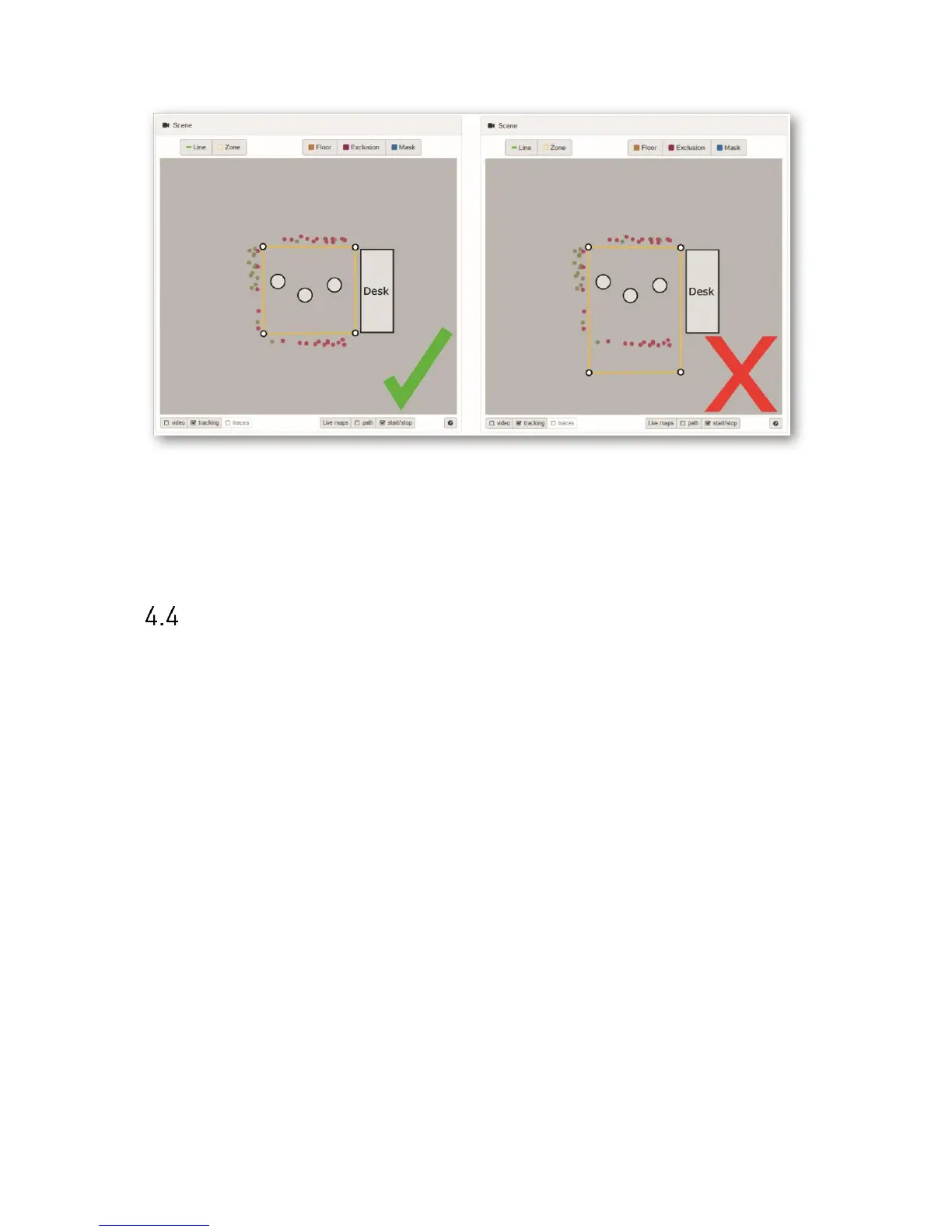
Figure 58: Start/stop points help identifying actual tracking area
The start/stop points (indicated as red and green points) show the limits of the sensor’s
tracking area. For optimal dwell time analysis, the dwell zone has to be placed inside the
sensor’s tracking area.
Time synchronization mechanism
The below flow diagram describes the time synchronization behavior depending on power or
internet connection loss.