FUEL INJECTION SYSTEM
7-31
EAS27400
TROUBLESHOOTING METHOD
The engine operation is not normal and the
engine trouble warning light comes on.
1. Check:
• Fault code number
▼▼▼▼▼▼▼▼▼ ▼ ▼▼▼▼▼▼▼▼▼ ▼ ▼▼▼▼ ▼ ▼▼▼▼ ▼▼▼
a. Check the fault code number displayed on
the meter.
b. Identify the faulty system with the fault code.
Refer to “Self-Diagnostic Function table”.
c. Identify the probable cause of the malfunc-
tion. Refer to “Diagnostic code table”.
▲▲▲▲▲▲▲▲▲ ▲ ▲▲▲▲▲▲▲▲▲ ▲ ▲▲▲▲ ▲ ▲▲▲▲ ▲▲▲
2. Check and repair the probable cause of mal-
function.
3. Perform ECU reinstatement action.
Refer to “Reinstatement method” of table in
“TROUBLESHOOTING DETAILS”.
4. Turn the main switch to “OFF” and back to
“ON”, then check that no fault code number is
displayed.
NOTE:
If fault codes are displayed, repeat steps (1) to
(4) until no fault code number is displayed.
5. Erase the malfunction history in the diagnos-
tic mode. Refer to “Sensor operation table
(Diagnostic code No. 62)”.
NOTE:
Turning the main switch to “OFF” will not erase
the malfunction history.
The engine operation is not normal but the
engine trouble warning light does not come
on.
1. Check the operation of following sensors and
actuators in the Diagnostic mode. Refer to
“Sensor operation table” and “Actuator oper-
ation table”.
If a malfunction is detected in the sensors or
actuators, repair or replace all faulty parts.
If no malfunction is detected in the sensors
and actuators, check and repair inner parts of
the engine.
EAS27420
DIAGNOSTIC MODE
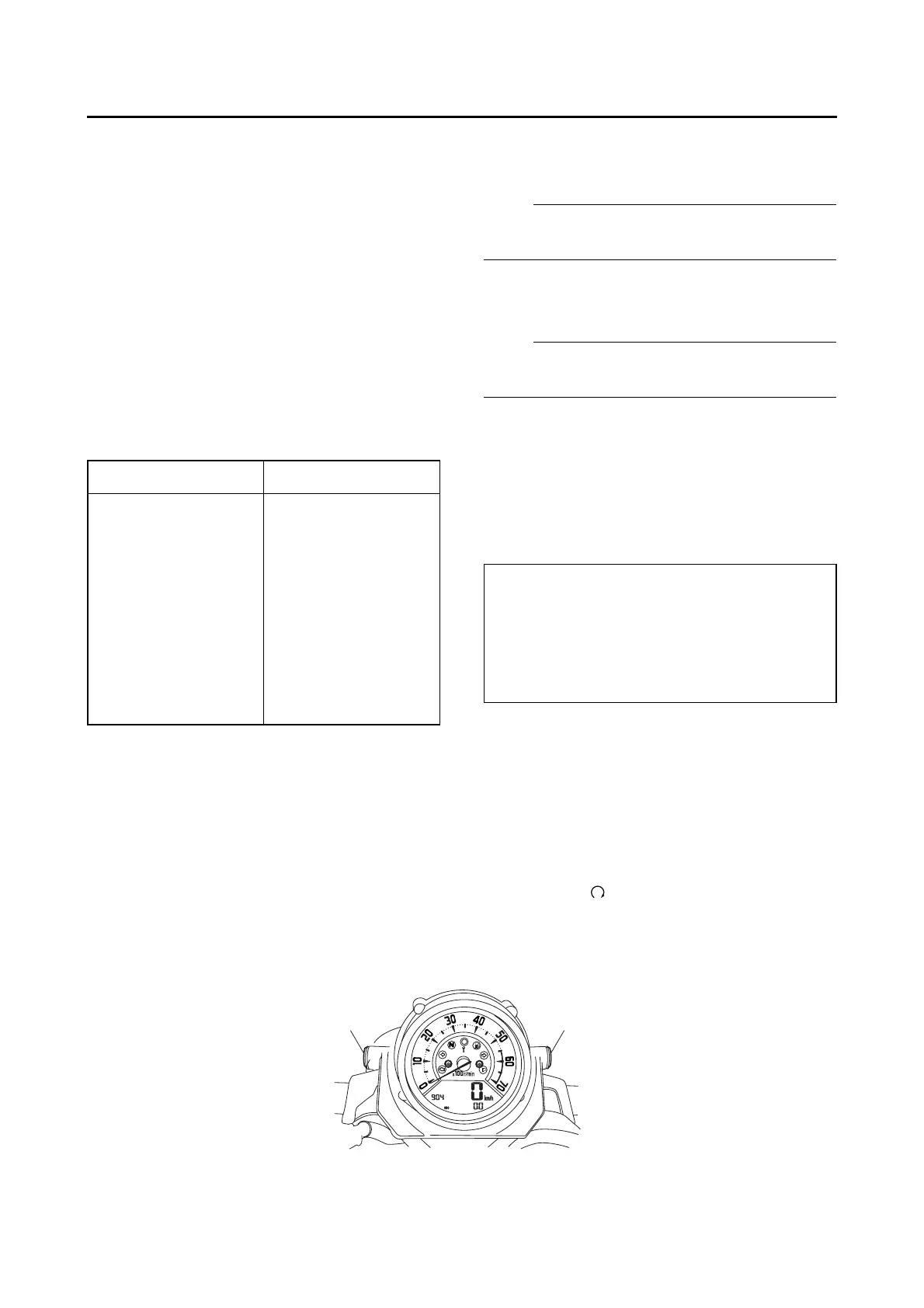
Setting the diagnostic mode
1. Turn the main switch to “OFF” and set the engine stop switch to “”.
2. Disconnect the wire harness coupler from the fuel pump.
3. Press and hold the “RESET” button, turn the main switch to “ON”, and continue to press the button
for 8 seconds or more.
Fault code No. No fault code No.
Check and repair.
Refer to “TROUBLE-
SHOOTING DE-
TAI LS ” on page 7-39.
Monitor the operation
of the sensors and
actuators in the
diagnostic mode.
Refer to “Sensor
operation table” and
“Actuator operation
table”.
Check and repair.
Refer to “Self-
Diagnostic Function
table”.
01: Throttle position sensor (throttle angle)
30: Cylinder-#1 left ignition coil
31: Cylinder-#2 left ignition coil
32: Cylinder-#1 right ignition coil
33: Cylinder-#2 right ignition coil
36: Injector #1
37: Injector #2
“RESET”
“SELECT”

 Loading...