ELECTRICAL COMPONENTS
7-101
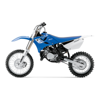
2. Check:
• Lean angle cut-off switch output voltage
Out of specification → Replace.
▼▼▼▼▼▼▼▼▼ ▼ ▼▼▼▼▼▼▼▼▼ ▼ ▼▼▼▼ ▼ ▼▼▼▼ ▼▼▼
a. Connect the lean angle cut-off switch coupler
to the lean angle cut-off switch.
b. Connect the pocket tester (DC 20 V) to the
lean angle cut-off switch coupler as shown.
c. Turn the lean angle cut-off switch to 65°.
d. Measure the lean angle cut-off switch output
voltage.
▲▲▲▲▲▲▲▲▲ ▲ ▲▲▲▲▲▲▲▲▲ ▲ ▲▲▲▲ ▲ ▲▲▲▲ ▲▲▲
EAS28150
CHECKING THE STATOR COIL
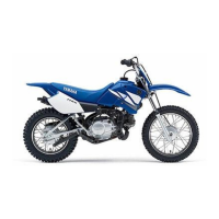
1. Disconnect:
• Stator coil coupler
(from the wire harness)
2. Check:
• Stator coil resistance
Out of specification → Replace the stator as-
sembly.
▼▼▼▼▼▼▼▼▼ ▼ ▼▼▼▼ ▼ ▼▼▼▼ ▼ ▼▼▼▼ ▼ ▼▼▼▼ ▼▼▼
a. Connect the pocket tester (Ω × 1) to the stator
coil coupler as shown.
b. Measure the stator coil resistance.
▲▲▲▲▲▲▲▲▲ ▲ ▲▲▲▲ ▲ ▲▲▲▲ ▲ ▲▲▲▲ ▲ ▲▲▲▲ ▲▲▲
EAS28170
CHECKING THE RECTIFIER/REGULATOR
1. Check:
• Charging voltage
Out of specification → Replace the rectifi-
er/regulator.
Lean angle cut-off switch output
voltage
Less than 65°: 0.4–1.4 V
More than 65°: 3.7–4.4 V
Pocket tester
90890-03112
Analog pocket tester
YU-03112-C
• Positive tester probe →
yellow/green “1”
• Negative tester probe →
black/blue “2”
Stator coil resistance
0.1280–0.1920 Ω
Pocket tester
90890-03112
Analog pocket tester
YU-03112-C
• Positive tester probe →
black “1”
• Negative tester probe →
black “2”
• Positive tester probe →
black “1”
• Negative tester probe →
black “3”
• Positive tester probe →
black “2”
• Negative tester probe →
black “3”
Charging voltage
14 V at 5000 r/min
BBB
2 31

 Loading...