6. Fuel Injection equipment
229
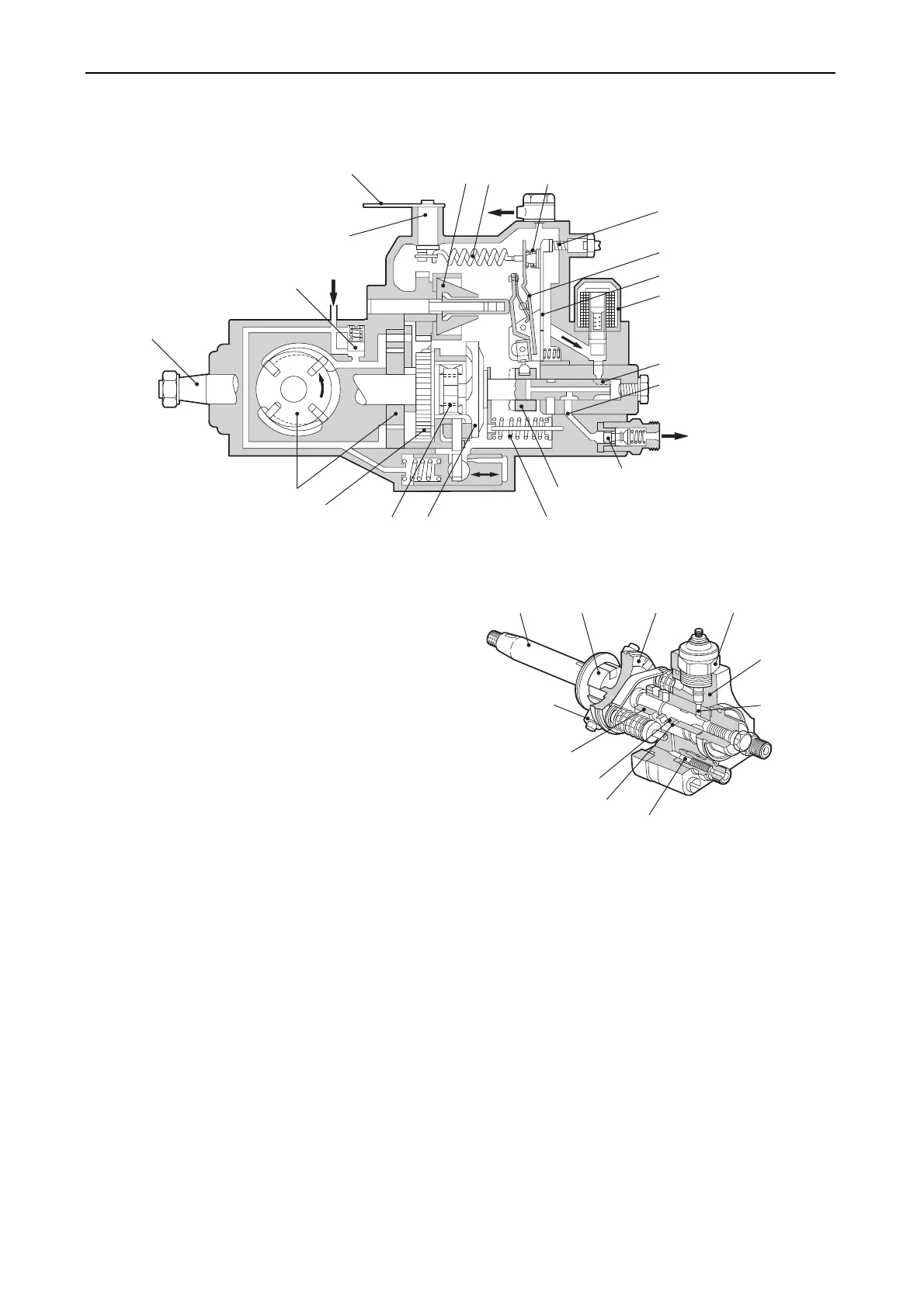
(2) Structure and function
1) Plunger
a) The drive shaft directly receives the engine
rotation by means of gears and transfers
the rotation to the cam disc through the
cross coupling. The positioning pin press-
fitted to the cam disc is also inserted in the
groove of the plunger flange, so that the
plunger and cam disc rotate in the same
direction.
The cam disc has a face cam to reciprocate
by a specified cam lift on the roller of the
roller holder assembly.
b) There are two plunger springs having
setting forces on the outside of the plunger.
The return the plunger which is pushed up
by the cam disc, in the descending
process. That is, the plunger rotates by
means of the drive shaft and reciprocates
by means of the cam disc.
When the fuel whose pressure is increased
by the plunger is sent to the outlet port, the
delivery valve opens to allow the fuel to be
injected into the combustion chamber
through the fuel injection nozzle.
Governor
springFlyweight
Control lever
Control lever shaft
Regulating valve
Drive shaft
Feed pump
Drive gear
Cross coupling
Cam disc
Plunger spring
Control sleeve
Delivery valve
Outlet port
Plunger
Magnetic valve
Governor lever assembly
Tension lever
Full load
adjusting screw
Idling spring
010346-00E
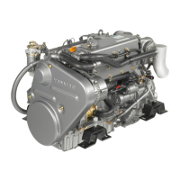
Drive shaft Cross coupling Cam disc Magnetic valve
Distributo
head
Delivery valve
Outlet port
Plunger barrel
Control
sleeve
Roller
Inlet port
010347-00E