12.2 A: Initialization Parameters
494 YASKAWA SIEPC71061753C GA500 Technical Manual
Conditions to Open and Close the Brake
Set L4-07 = 0 [Speed Agree Detection Selection = No Detection during Baseblock] to open and close the holding
brake.
When L4-07 = 1 [Detection Always Enabled], the output frequency increases when you input the Run command
although the external baseblock command is input. Because of this, speed detection operates and will open the
brake signal.
• Set Related Parameters
Table 12.20 shows examples of parameter settings to use the terminal P2-C2 as the holding brake open and
close signal.
Table 12.20 Holding Brake Open and Close Signal Setting Example
Brake Open and Close Signal Brake Open and Close Level Adjust
Applicable Control Methods
(A1-02 Settings)
Signal Name Parameter Settings Signal Name Parameter Settings
V/f
(0)
OLV
(2)
Frequency (FOUT) Detection 2
L4-07 = 0 Speed Agree Detection Level L4-01 = 1.0 Hz to 3.0 Hz
*1
x x
H2-03 = 5 Speed Agree Detection Width L4-02 = 0.0 Hz to 0.5 Hz
*1 When A1-02 = 2 [Open Loop Vector], it is the usual setting range. When A1-02 = 0 [V/f Control], set L4-01 to the rated slip
frequency of the motor + approximately 0.5 Hz. If you set the value too low, motor torque will not be sufficient and it will cause
motor rollback. Set the parameter to agree with these conditions at the same time. If you set the value too high, it will cause
overshoot at start.
• L4-01 > E1-09 [Minimum Output Frequency]
• L4-01 > L4-02 [Speed Agree Detection Width]
*2 Use L4-02 to adjust the detection width of Frequency Detection 2. If rollback occurs when the motor stops, change the frequency to
approximately 0.1 Hz.
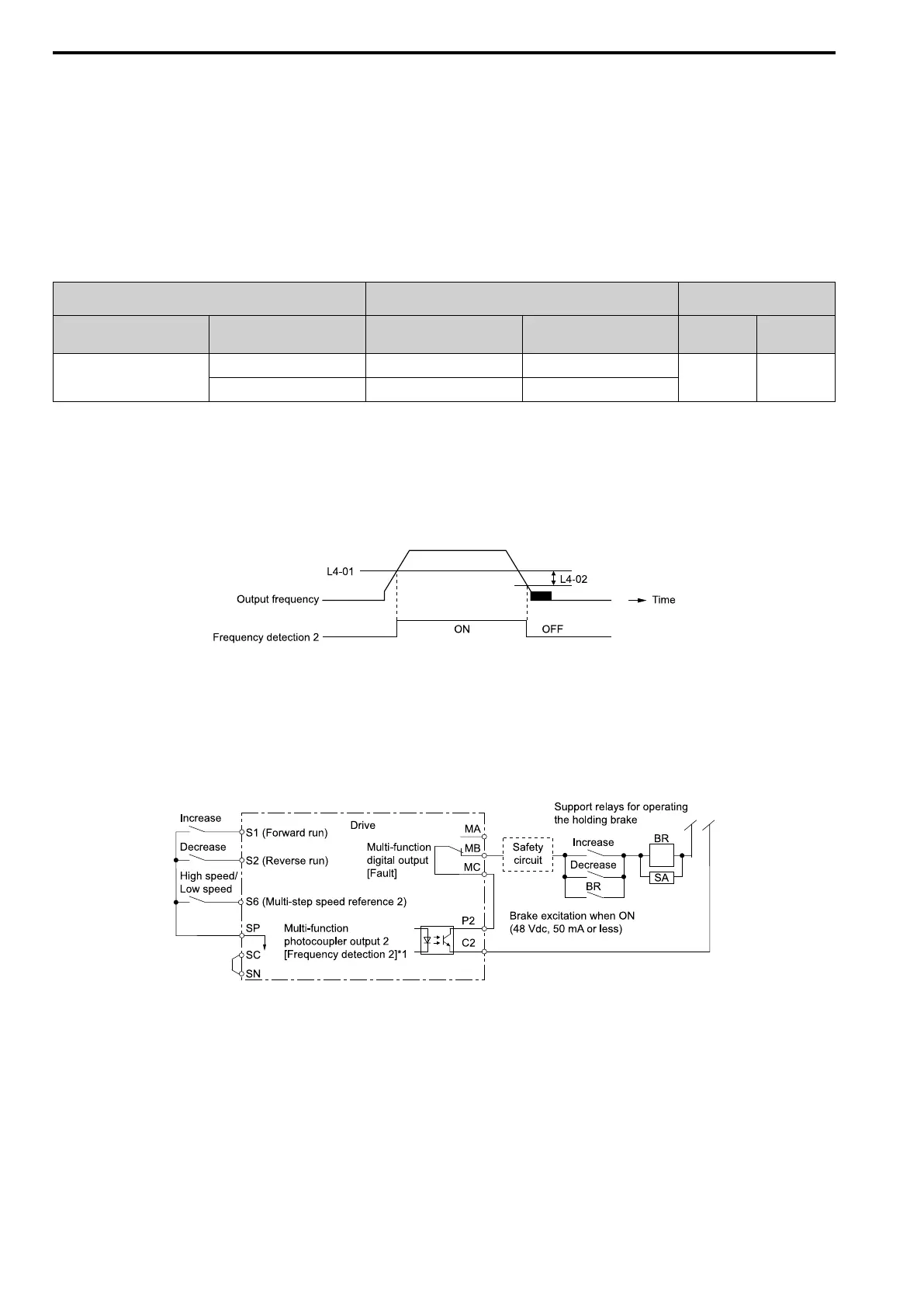
Figure 12.1 Frequency Detection 2
Sequence Circuit Configuration
Use these conditions to set the circuit for the open/close sequence of the holding brake:
• Set the sequence-side operation conditions to activate terminal P2-C2 and open the holding brake.
• Set the sequence to close the holding brake in an emergency if the drive detects a fault.
• Set the sequence to open the holding brake when you enter an increase or decrease command.
Figure 12.2 Sequence Circuit Configuration Diagram
*1 L4-07 = 0 [Speed Agree Detection Selection = No detection during baseblock]
Time Chart
Figure 12.3 shows the open and close sequence of the holding brake.

 Loading...


