5.2 b: Application
222 YASKAWA SIEPYAIH6B01A HV600 AC Drive Bypass Technical Reference
Refer to Custom Units on page 213 for more information about available selections.
■ b5-70: System Unit Custom Character 3
No.
(Hex.)
Name Description
Default
(Range)
b5-70
(3C21)
System Unit Custom
Character 3
Sets the third character of the custom unit display when b5-46 = 49 [PID Unit Display Selection =
Custom (B5-68~70)].
41
(20 - 7A)
Refer to Custom Units on page 213 for more information about available selections.
■ b5-71: Min PID Transducer Scaling
No.
(Hex.)
Name Description
Default
(Range)
b5-71
(3C22)
Min PID Transducer Scaling Sets the minimum PID level corresponding to the lowest analog input signal level. 0.00
(-99.99 - +99.99)
Note:
• To enable this parameter, you must set b5-71 < b5-38 [PID User Unit Display Scaling]. If you set b5-71 > b5-38, the drive will disable all
PID analog inputs.
• Parameters b5-46 [PID Unit Display Selection], b5-38, and b5-39 [PID User Unit Display Digits] set the unit, range, and resolution.
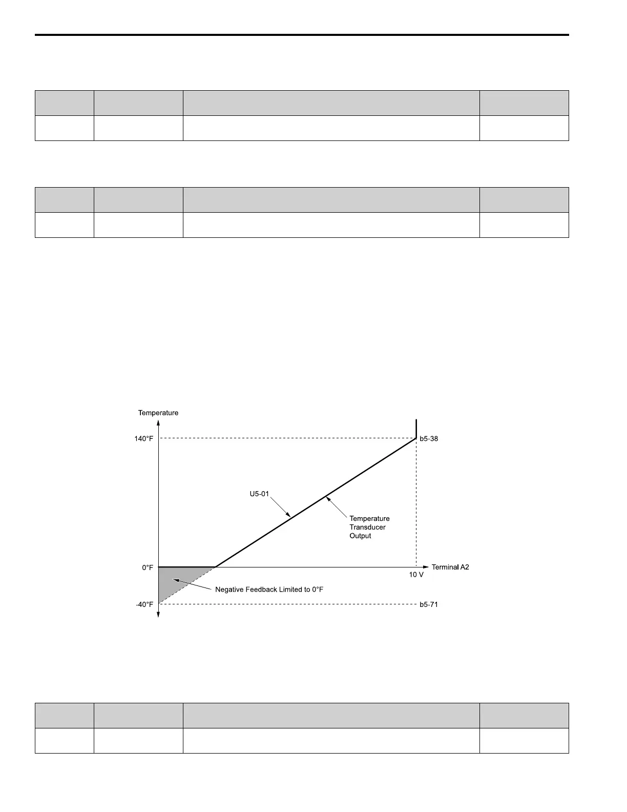
When you set b5-71 < 0, the drive appropriately scales the setpoint and feedback values of the drive, but internally
limits to 0 when the reported value from the transducer is negative.
Figure 5.26 shows an example of the transducer scaling lower limit when:
• b5-01 = 1 [PID Mode Setting = Standard]
• b5-46 = 3 [°F: Fahrenheit]
• b5-71 < 0.00
• H3-09 = 0 [Terminal A2 Signal Level Select = 0-10V (LowLim=0)]
• H3-10 = B [Terminal A2 Function Selection = PID Feedback]
b5-38: PID User Unit Display Scaling
b5-71: Min PID Transducer Scaling
U5-01: PID Feedback
Figure 5.26 Transducer Scaling Lower Limit
■ b5-82: Feedback Loss 4~20mA Detect Sel
No.
(Hex.)
Name Description
Default
(Range)
b5-82
(31B0)
Feedback Loss 4~20mA
Detect Sel
Sets the drive to do a 4 to 20 mA wire-break detection on the analog input set for PID feedback. 2
(0 - 3)

 Loading...


