Network Communications
10
10.4 APOGEE FLN (P1) Communications
YASKAWA SIEPYAIH6B01A HV600 AC Drive Bypass Technical Reference 721
CMD REV.STOP (Point 22) can be commanded to run the bypass in the reverse direction. FWD.REV (Point 21)
shows the current direction of the bypass rotation.
NOTICE: Damage to Equipment. Make sure that the motor direction is correct when you set b1-04 = 0 [Reverse Operation
Selection = Reverse Enabled]. Incorrect motor direction can cause damage to HVAC equipment.
• Lock the Bypass Panel
Locking the panel prevents the user from using the HAND and OFF keys locally at the drive panel. LOCK PANEL
(Point 33) can be commanded to lock and unlock the panel.
• Digital Outputs
MULTI OUT 1 (Point 40), MULTI OUT 2 (Point 41), and MULTI OUT 3 (Point 42) are physical digital outputs on
the bypass. Their purpose depends on how the bypass has been set-up. The bypass can be programmed so that these
points can display various limits, warnings, and status conditions. Some examples include frequency limit, over
current, and motor over temperature fault.
• Loop Gain
PID P GAIN (Point 63) and PID I TIME (Point 64) are the gain and integral time parameters similar to the P and I
gains in the APOGEE FLN Terminal Equipment Controllers. The PI loop of the drive is structured differently than
the Siemens loop, so there is not a one-to-one correspondence between the gains.
• Reading and Resetting Faults
OK.FAULT (Point 93) shows the current status of the drive. FAULT CODE (Point 17) contains the code for the
most current fault. LST FLT CODE (Point 66) contains the code for the previous fault. See table below for
descriptions of the fault codes. The drive can be reset back to OK mode by commanding RESET FAULT (Point 94)
to RESET.
◆ APOGEE FLN Point Database
This section shows the APOGEE FLN point database for Application 2721.
■ APOGEE FLN Point List Summary
This database is for APOGEE FLN Application 2721 and features 92 logical points: 29 Logical Analog Inputs (LAI),
31 Logical Analog Outputs (LAO), 19 Logical Digital Inputs (LDI) and 13 Logical Digital Outputs (LDO). These
points set, control, or monitor the operation of the drive.
Information to consider when referencing this table:
1. This application does not use the points that are not listed.
2. A single value in a column means that the value is the same in English units and in SI units.
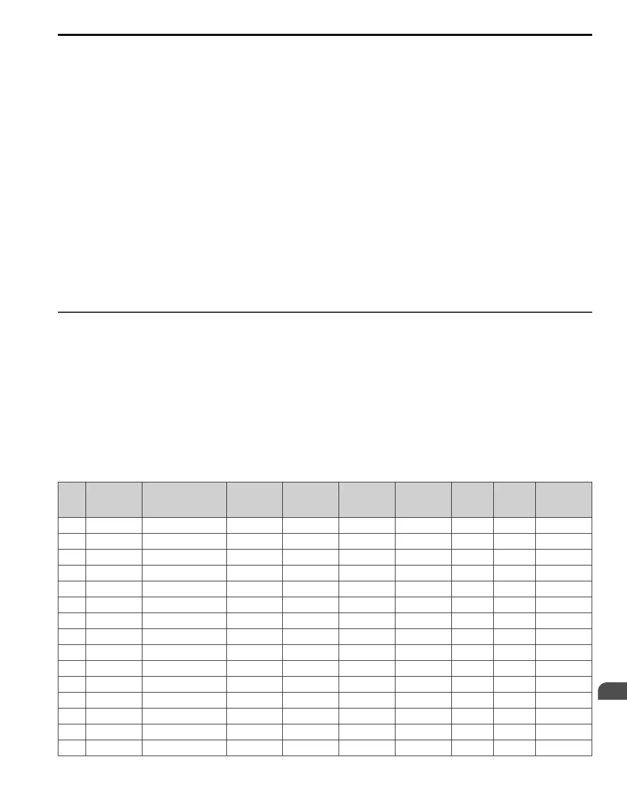
Table 10.10 APOGEE FLN Application 2721 Point Number Summary
Point
No.
Point
Type
Point Name
Factory
Default
(SI Units)
Eng. Units
(SI Units)
Slope
(SI Units)
Intercept
(SI Units)
On Text Off Text Parameter
01 LAO CTLR ADDRESS 31 - 1 0 - - H5-01
02 LAO APPLICATION 2721 - 1 0 - - -
03
*1
LAI FREQ OUTPUT 0 Hz 0.01 0 - - U1-02
04
*1
LAI PCT OUTPUT 0 % 0.01 0 - - -
05
*1
LAI SPEED 0 RPM 0.01 0 - - -
06
*1
LAI CURRENT 0 A 0.01/0.1 0 - - UB-01
07
*1
LAI TORQUE 0 % 0.1 0 - - -
08
*1
LAI POWER 0 kW 0.1 0 - - U1-08
09
*1
LAI DRIVE TEMP 0 ° C/F 1 0 - - U4-08
10
*1
LAI DRIVE KWH 0 kWh 0.1 0 - - U4-10
11
*1
LAI MWH 0 mWh 1 0 - - U4-11
12
*1
LAI RUN TIME 0 h 1 0 - - U4-01
13
*1
LAI DC BUS VOLT 0 V 1 0 - - U1-07
14
*1
LAI AC OUT VOLT 0 V 0.1 0 - - U1-06
15 LAI PAR N9.01 0 A 0.01/0.1 0 - - -

 Loading...


