10.6 MEMOBUS/Modbus Communications
750 YASKAWA SIEPYAIH6B01A HV600 AC Drive Bypass Technical Reference
7. De-energize the bypass.
8. Disconnect the jumper from Step 4. Set Z2-06 to its initial function.
Self-Diagnostics is complete and the bypass returns to its usual function.
◆ Communications Data Table
Command Data on page 750 and Monitor Data on page 754 show the communications data. The data types are
command data, monitor data, and broadcast message.
Refer to the Parameter List for parameter communications registers.
■ Command Data
Note:
When writing a command register that contains reserved bits, always write reserved bits to a “0”. Do not write to reserved registers or
monitor registers.
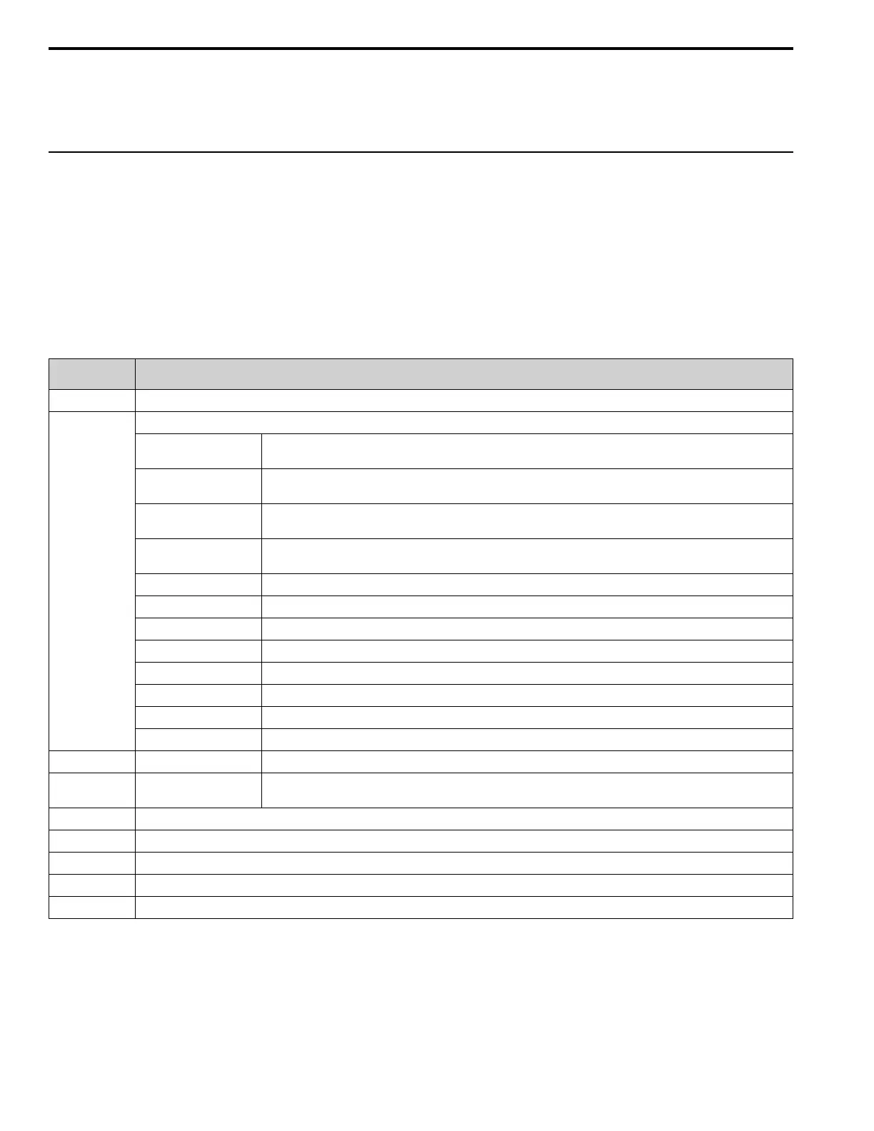
Table 10.30 MEMOBUS/Modbus Communications Command Data
Register No.
(Hex.)
Description
0000 Reserved
0001
Run command, multi-function input command
bit 0
1: Forward run, 0: Stop
1: Run, 0: Stop
bit 1
1: Reverse run, 0: Stop
1: Reverse, 0: Forward run
bit 2
External fault
1: EF0 [Option Card External Fault]
bit 3
Fault Reset Procedure
1: Reset command
bit 4 Drive Multi-function input 1
bit 5 Drive Multi-function input 2
bit 6 Drive Multi-function input 3
bit 7 Drive Multi-function input 4
bit 8 Drive Multi-function input 5
bit 9 Drive Multi-function input 6
bit A Drive Multi-function input 7
bit B - F Reserved
0002 Frequency reference o1-03 [Frequency Display Unit Selection] (unsigned) sets the units.
0003 Output voltage gain
Units: 0.1 %
Setting range: 20 (2.0%) to 2000 (200.0%), the default value at energize: 1000 (100.0%)
0004 Torque reference/torque limit (0.1% signed)
0005 Torque compensation (0.1% signed)
0006 PID setpoint (0.01% signed)
0007 Setting for the drive multi-function analog monitor output terminal FM (10 V/4000H)
0008 Setting for the drive multi-function analog monitor output terminal AM (10 V/4000H)

 Loading...


