HB700 | CPU | PMC921xEx | en | 24-04 131
Deployment CPU iC921xM-FSoE
Response times > There is no error
Maximum expected
response time in the case
without errors
NOTICE
If your CPU is still in the Hard fail safe state after a power cycle and this
does not change even after a reset ⮫
‘MRESET and reset to factory set-
tings’...page 127, please contact the Yaskawa hotline.
5.12 Response times
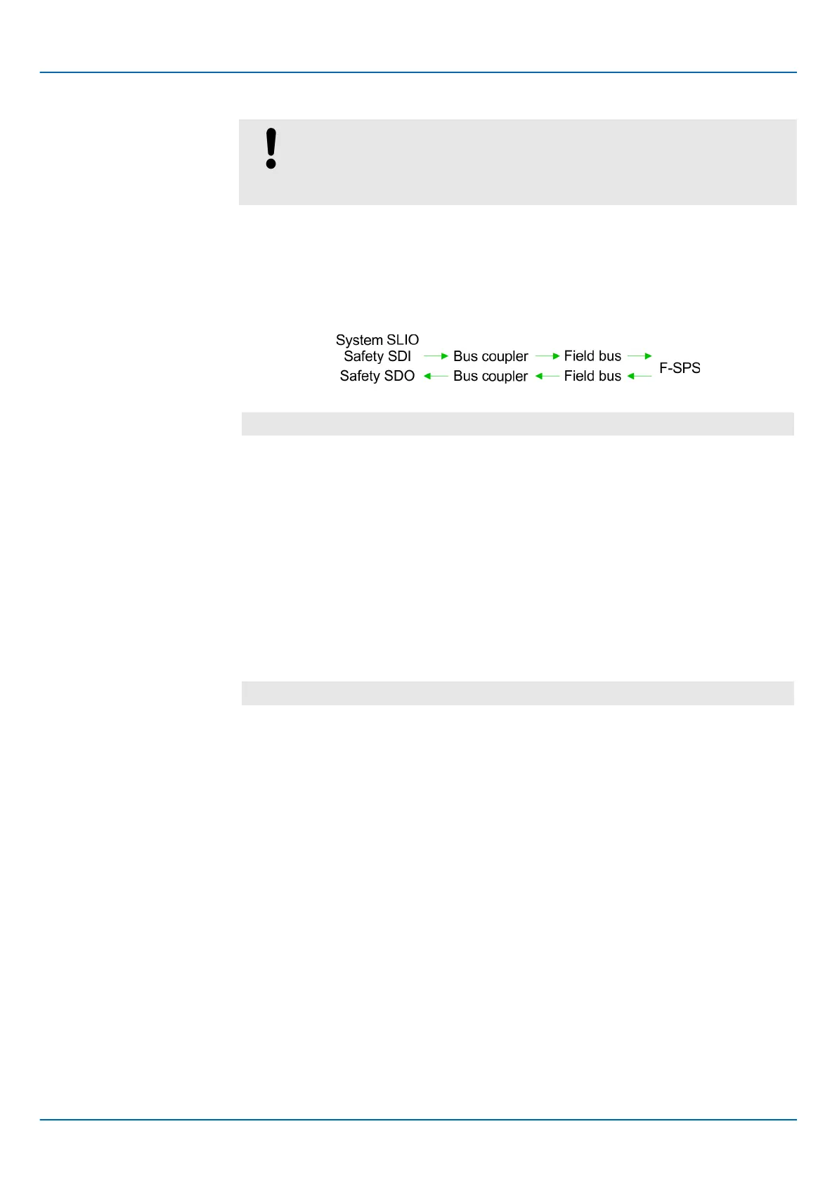
5.12.1 There is no error
Without an error
, it is assumed that none of the watchdogs respond and the passage of
a signal from the input connector of a safety input module to the output connector of a
safety output module is considered:
T
maxNF
= TI
ST
+ TI
WCDT
+ TI
Slave
+ TI
BUS
+ T
CL
+ T
FPROG
+ T
O
BUS
+ TO
Slave
+ TO
WCDT
⮫‘Designations’
...page 135
T
maxNF
Max. response time without errors (max No Fault).
TI
ST
Input smoothing time of the inputs of the safety SDI (Smoothing Time).
TI/TO
WCDT
Max. response time without errors (Worst Case Delay Time).
TI
Slave
Max. Response time of the decentralised periphery system, i.e. delay caused
by the FSoE EtherCA
T coupler and the backplane bus.
TI
BUS
EtherCAT cycle time for EtherCAT bus communication. The EtherCAT cycle
time results from the cycle times of all connected EtherCAT slaves.
T
CL
Cycle time of the safety CPU.
T
FPROG
Cycle time safety program.
For plant design sensor and actuator run times are to be taken into account:
T
maxNFSA
= T
SensorDL
Y
+ T
maxNF
+ T
ActuatorDLY
⮫‘Designations’
...page 135
T
maxNFSA
Max. response time without errors with sensor and actuator
(max No Fault Sensor Actuator).
T
SensorDL
Y
Delay time of the sensor (Sensor DeLaY).
T
maxNF
Max. response time without errors (max No Fault).
T
ActuatorDLY
Delay time of the actuator (Actuator DeLaY).

 Loading...


