HB700 | CPU | PMC921xEx | en | 24-04 35
Wiring > Wiring System SLIO periphery
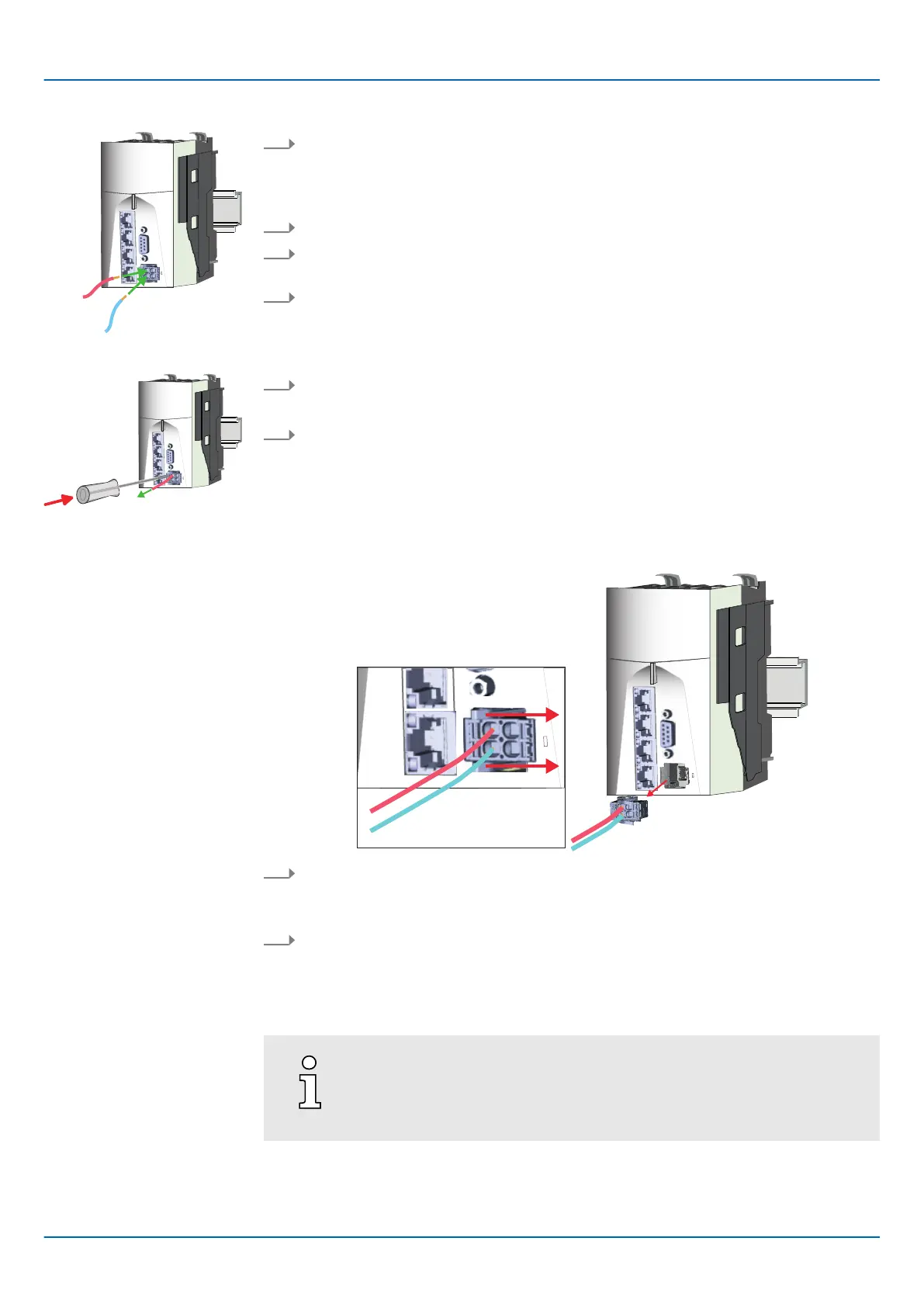
Remove wire
Remove connector
1. Insert through the round connection hole of the according contact your prepared
wire until it stops, so that it is fixed.
🡆 By pushing the contact spring opens, thus ensuring the necessary contact pres-
sure.
2. Determine the pin position according to the pin assignment.
3. Connect the positive pole (+) of your external DC 24V power supply to pin 1 or pin
2.
4. Connect the minus pole (0V) of your external DC 24V power supply to pin 3 or pin
4.
🡆 As soon as the CPU is power supplied, the associated LED lights up.
The wire is to be removed by means of a screwdriver with 2.5mm blade width.
1. Press with your screwdriver vertically at the release button.
🡆 The contact spring releases the wire.
2. Pull the wire from the round hole.
Y
ou have the option to remove the connector of the power supply, e.g. for a module
change with fixed wiring. For this the connector has a locking lever. The connector is
removed as follows:
1. Remove connector:
By pressing the release button as shown, the connector is released and can be
removed.
2. Plug connector:
The connector is plugged by plugging it directly into the release lever
. Here, the
locking levers return to their original position.
2.5.2 Wiring System SLIO periphery
When using System SLIO modules, you must always mount the power
module 007-1AB00 - DC 24V 10A, because the CPU does not provide a
power section supply due to the system.

 Loading...


