68 HB700 | CPU | PMC921xEx | en | 24-04
Structure > Operating mode switch
Status
LED
PN-C ER
red
PN-D ER
red
Description
not relevant: X
1) The status depends on the operating mode of the CPU.
LEDs RJ45 jacks
LED Color Function
green The according RJ45 jack is physically connected to the Ethernet.
green
flickers
The LED flickers when there is data traffic.
LED power supply
LED Color Function
green The CPU is power supplied.
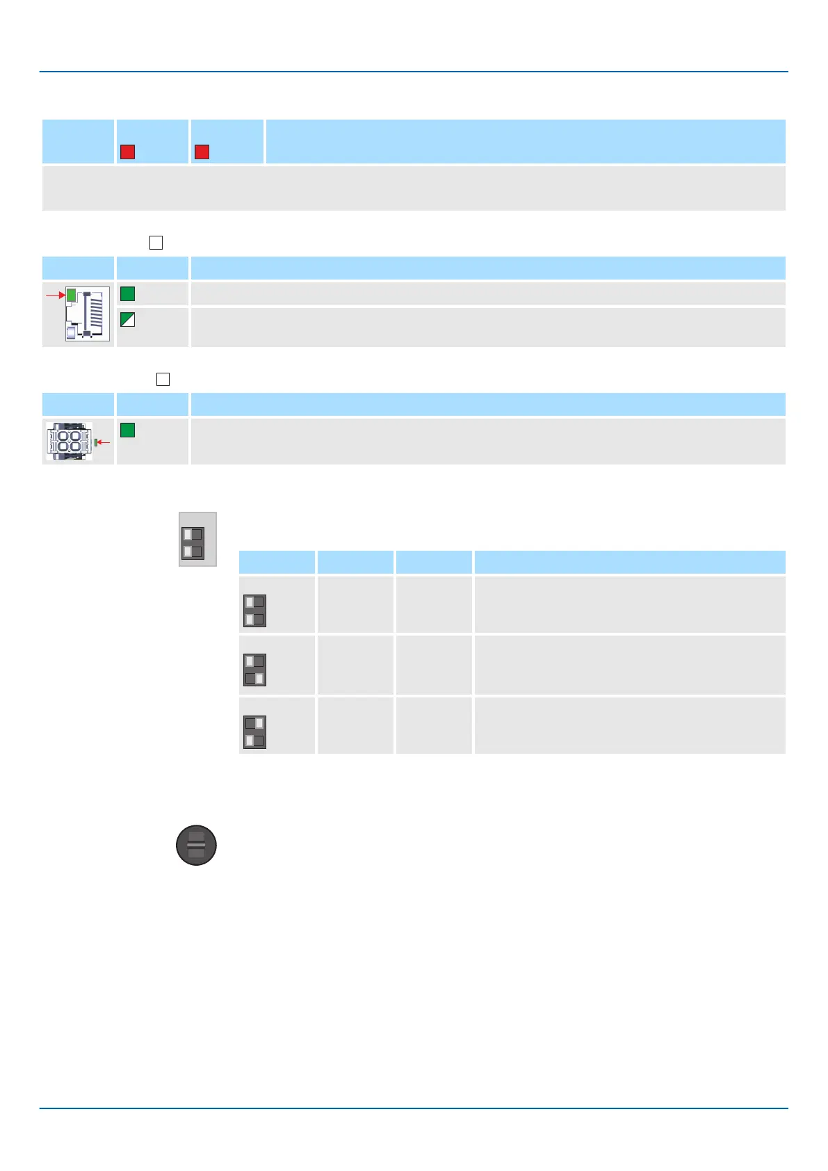
3.2.6 DIP switch
Y
ou can trigger the following actions of the CPU with the 2-fold DIP switch under the front
flap:
S1 S1-1 S1-2 Action
OFF OFF After PowerON the CPU starts in Standard Mode
- Default setting.
OFF ON After PowerON the CPU executes a reset to fac-
tory settings type 1.
⮫
‘Reset to factory settings type 1’...page 97
ON OFF After PowerON the CPU starts in Safe Mode.
⮫
‘Safe Mode’...page 98
3.2.7 Operating mode switch
■ With the operating mode switch, you can select between the operating modes ST
(STOP) and RN (RUN) on the CPU.
■ With the button position MR (Memory Reset) you can request a reset of the CPU in
dif
ferent levels. ⮫‘MRESET and reset to factory settings’...page 97

 Loading...


