62 HB700 | CPU | PMC921xEx | en | 24-04
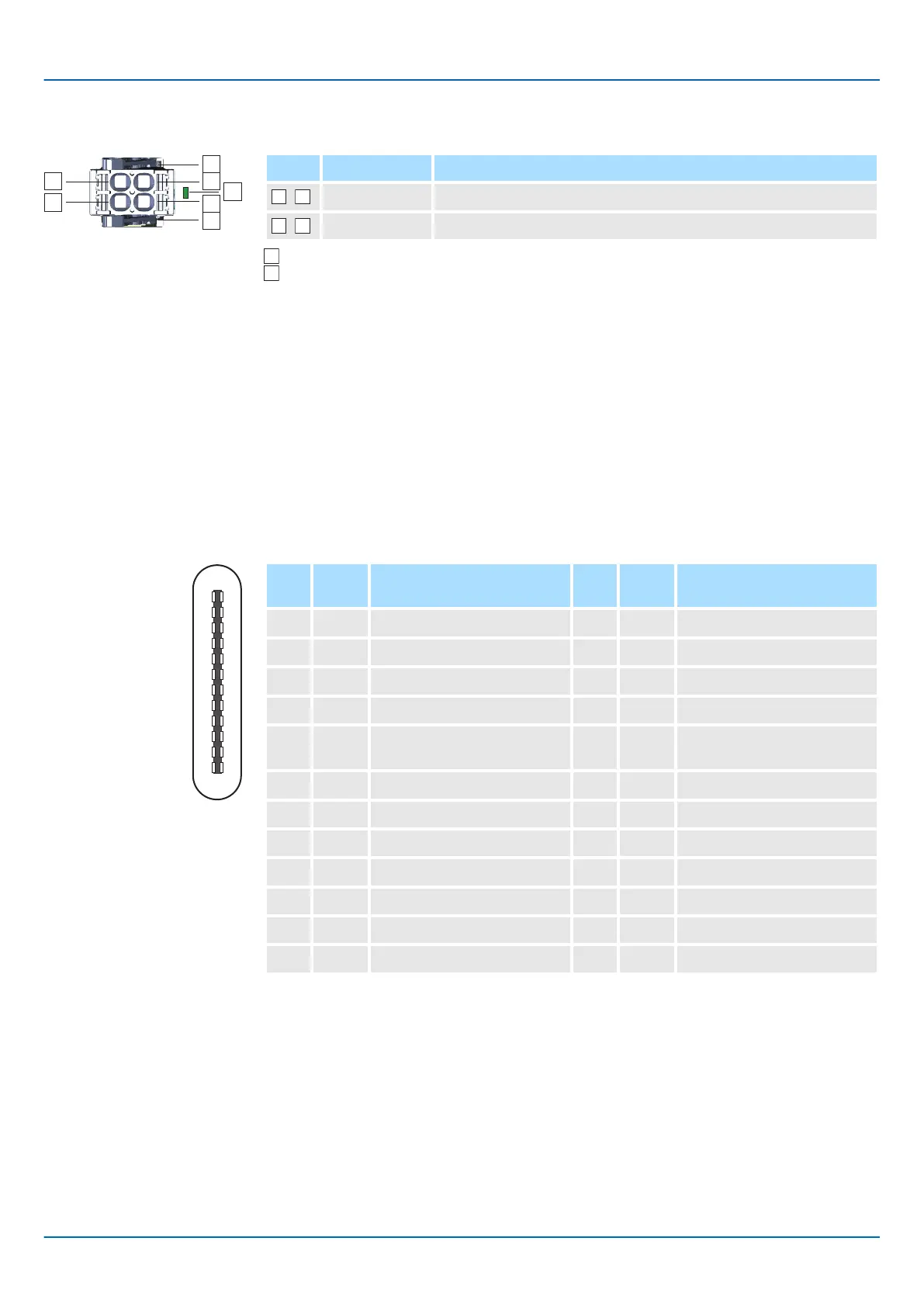
X6: Power supply
X7: USB-C
1
A
12
B
211
310
49
58
67
76
85
94
103
112
121
2-pin connector:
Pos. Signal Description
,
DC 24V Plus DC 24V power supply, bridged in the plug.
,
0V Ground DC 24V power supply, bridged in the plug.
LED indication for power supply.
Locking lever
The CPU has an integrated power supply:
■ The power supply is to be provided with DC 24V, max. 1.5A. For this, the DC 24V
connection is used.
■ Both the CPU electronics and the electronics of the System SLIO periphery modules,
which are connected via the SliceBus, can be supplied with the supply voltage. An
additional power module is required for the power section supply of the System SLIO
periphery modules.
■ The power supply is protected against reverse polarity and overcurrent.
■ You have the option to remove the connector of the power supply, e.g. for a module
change with fixed wiring. For this the connector has a locking lever
. ⮫‘Wiring
CPU’...page 34
■ For easy wiring, each pole on the connector is 2-fold.
24pin USB-C jack:
Pin
A
Signal Description Pin
B
Signal Description
1 GND Ground 1 GND Ground
2 TX1+ High speed data path 1 + 2 TX2+ High speed data path 2 +
3 TX1- High speed data path 1 - 3 TX2- High speed data path 2 -
4 VBUS Voltage + 5V 4 VBUS Voltage +5V
5 CC1 Control channel 1 for
connector orientation
5 CC2 Control channel 2 for
connector orientation
6 D+ USB 2.0 data + 6 D+ USB 2.0 data +
7 D- USB 2.0 data - 7 D- USB 2.0 data -
8 n.c. reserved 8 n.c. reserved
9 VBUS Voltage +5V 9 VBUS Voltage +5V
10 RX2- High speed data path 2 - 10 RX1- High speed data path 1 -
11 RX2+ High speed data path 2 + 11 RX1+ High speed data path 1 +
12 GND Ground 12 GND Ground
■ The interface is located under the front flap.
■ The interface is not relevant for customer applications.
■ The interface supports the USB 2.0 protocol and is used exclusively as a service
interface.

 Loading...


