YASKAWA ELECTRIC SIEP C710606 10A YASKAWA AC Drive - V1000 PRELIM. Programming Manual 109
1.5 E: Motor Parameters
Parameter Details
1
1.5 E: Motor Parameters
E parameters cover motor related settings.
◆ E1: V/f Characteristics
■ E1-01: Input Voltage Setting
Set the input voltage parameter to the nominal voltage of the AC power supply. This
parameter adjusts the levels of some protective features of the drive (overvoltage, Stall
Prevention, etc.).
NOTICE: Set parameter E1-01 to match the input voltage of the drive. Drive input voltage (not motor
voltage) must be set in E1-01 for the protective features of the drive to function properly. Failure to comply
could result in improper drive operation.
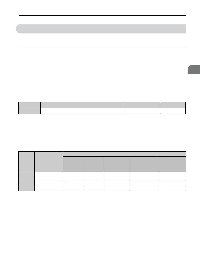
E1-01 Related Values
The input voltage setting determines the over-/undervoltage detection level and the
operation levels of the braking transistor as well as the KEB function and the overvoltage
suppression function.
Note: The braking transistor operation levels are valid for the drive internal braking transistor. If an
external CDBR braking chopper is used, refer to the instruction manual of that unit.
■ V/f Pattern Settings
The drive utilizes a set V/f pattern to determine the appropriate output voltage level for each
relative to the frequency reference.
There are 15 different preset V/f patterns to select from with varying voltage profiles,
saturation levels (frequency at which maximum voltage is reached), and maximum
No.
<1> The setting range and default value shown here are for 200 V class drives. Double this for 400 V class units.
Parameter Name Setting Range Default
E1-01 <1> Input Voltage Setting 155 to 255 V 200 V
Voltage
Setting Value of
E1-01
(Approximate Values)
OV
Detection
Level
BTR
Operation
Level
UV Detection
Level
(L2-05)
Desired DC Bus
Voltage during
KEB (L2-11)
OV Suppres-
sion/ Stall Pre-
vention Level
(L2-17)
200 V
Class
all settings 410 V 394 V
190 V (single
phase = 160 V)
240 V 370 V
400 V
Class
setting >= 400 V 820 V 788 V 380 V 480 V 740 V
setting < 400 V 740 V 708 V 350 V 440 V 660 V

 Loading...


