A.2 Parameter Table
364 YASKAWA ELECTRIC SIEP C710606 10A YASKAWA AC Drive - V1000 PRELIM. Programming Manual
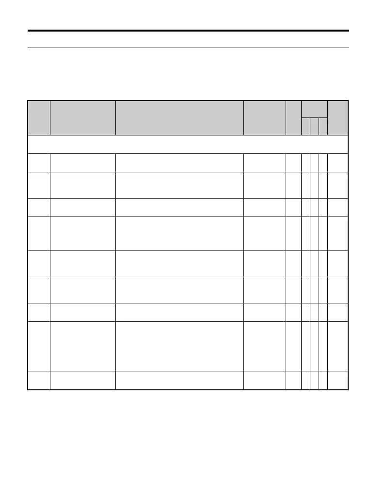
◆ U: Monitors
Monitor parameters allow the user to view drive status, fault information, and other
information about drive operation.
No. Name Description
Analog
Output Level
Unit
Control
Mode
Addr.
Hex
V/f
O
LV
P
M
U1: Operation Status Monitors
Use U1 monitors to display the operation status of the drive.
U1-01 Frequency Reference Monitors the frequency
10 V: Max
frequency
0.01
Hz
AAA 40
U1-02 Output Frequency
Displays the output voltage. Display units are
determined by o1-03.
10 V: Max
frequency
0.01
Hz
<27>
AAA 41
U1-03 Output Current Displays the output current.
10 V: Drive
rated current
0.01
A
AAA 42
U1-04 Control Mode
Control method set in A1-02.
0: V/f without PG
2: Open Loop Vector (OLV)
5: PM Open Loop Vector (PM)
No output
signal
available
–AAA43
U1-05 Motor Speed
Displays the motor speed feedback. Display
units are determined by o1-03.
10 V:
Maximum
speed
0.01
Hz
–A– 44
U1-06
Output Voltage
Reference
Displays the output voltage.
10 V: 200
Vrms
(400 Vrms)
0.1 V A A A 45
U1-07 DC Bus Voltage Displays the DC bus voltage.
10 V: 400 V
(800 V)
1 V A A A 46
U1-08 Output Power
Displays the output voltage (this value is
determined internally).
10 V:
Drive
capacity (kW)
(max. motor
capacity
allowed)
<27> AAA 47
U1-09 Torque Reference
Monitor of internal torque reference value for
Open Loop Vector (OLV) control
10 V: Motor
rated torque
––A–48

 Loading...


