1.3 C: Tuning
92 YASKAWA ELECTRIC SIEP C710606 10A YASKAWA AC Drive - V1000 PRELIM. Programming Manual
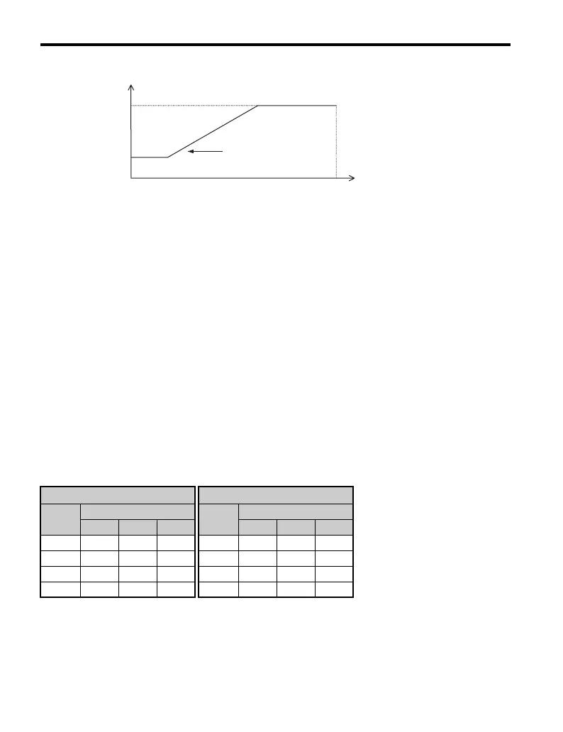
Figure 1.30
Figure 1.30 Carrier Frequency Changes Relative to Output Frequency
K is a coefficient determined by the value of C6-03:
• 10.0 kHz > C6-03 greater than or equal to 5.0 kHz: K=2
• 5.0 kHz > C6-03: K=1
• C6-03 greater than or equal to 10.0 kHz: K=3
Note: 1. A carrier frequency error (oPE11) will occur when the carrier frequency proportional gain is greater
than 6 while C6-03 is less than C6-04.
2. When C6-05 is set lower than 7, C6-04 is disabled and the carrier frequency will be fixed to the value
set in C6-03.
■ Rated Current Depending on Carrier Frequency
The tables below show the drive output current depending on the carrier frequency settings.
The 2 kHz value is equal to the Normal Duty rated current, the 8/10 kHz value is equal to the
Heavy Duty rated current. The carrier frequency determines the output current linearly. Use
the data below to calculate output current values for carrier frequencies not listed in the
tables.
Note: In Heavy Duty mode the maximum rated output current is equal to the 8/10 kHz value, even if
the carrier frequency is reduced.
Table 1.27 Drives with Heavy Duty Default Carrier Frequency of 10 kHz
200 V Single Phase Units 200 V Three Phase Units
Model
VZA~
Rated Current [A]
Model
VZA~
Rated Current [A]
2 kHz 10 kHz 15 kHz 2 kHz 10 kHz 15 kHz
B0P1 1.2 0.8 0.6 20P1 1.2 0.8 0.6
B0P2 1.9 1.6 1.3 20P2 1.9 1.6 1.3
B0P4 3.5 3.0 2.4 20P4 3.5 3.0 2.4
B0P7 6.0 5.0 4.0 20P7 6.0 5.0 4.0
C6-03
C6-04
Output frequency
Output
frequency
E1-04
Max. Output Frequency
Carrier frequency
x C6-05 x K*

 Loading...


