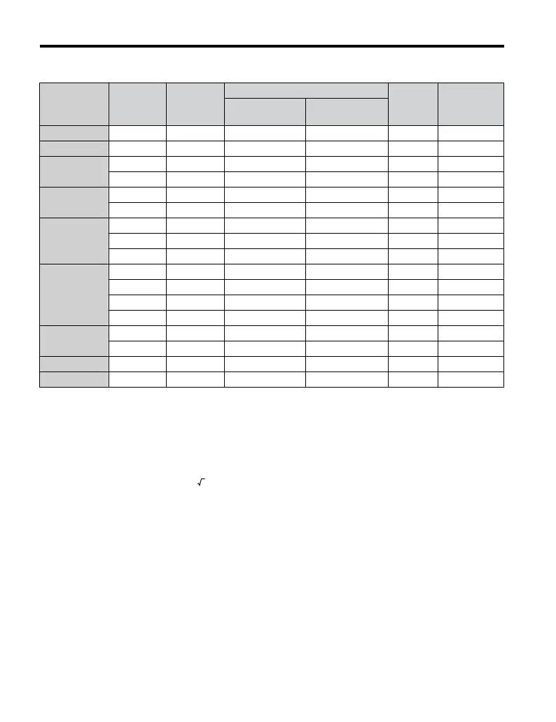
Table C.5 Closed-Loop Crimp Terminal Sizes
Wire Gauge
Terminal
Screws
Crimp
Terminal
Model
Number
Tool
Insulation
Cap
Model No.
Code
<1>
Machine No. Die Jaw
18 AWG M3.5 R1.25-3.5 YA-4 AD-900 TP-003 100-066-217
16 AWG M3.5 R1.25-3.5 YA-4 AD-900 TP-003 100-066-217
14 AWG
M3.5 R2-3.5 YA-4 AD-900 TP-003 100-066-218
M4 R2-4 YA-4 AD-900 TP-003 100-054-028
12 / 10 AWG
M4 R5.5-4 YA-4 AD-900 TP-005 100-054-029
M5 R5.5-5 YA-4 AD-900 TP-005 100-054-030
8 AWG
M4 8-4 YA-4 AD-901 TP-008 100-054-031
M5 R8-5 YA-4 AD-901 TP-008 100-054-032
M8 R8-8 YA-4 AD-901 TP-008 100-061-111
6 AWG
M4 14-4 YA-4 AD-902 TP-014 100-66-220
M5 R14-5 YA-4 AD-902 TP-014 100-054-034
M6 R14-6 YA-5 AD-952 TP-014 100-051-261
M8 R14-8 YA-5 AD-952 TP-014 100-054-035
4 AWG
M6 R22-6 YA-5 AD-953 TP-022 100-051-262
M8 R22-8 YA-5 AD-953 TP-022 100-051-263
3 AWG M8 R38-8 YA-5 AD-954 TP-038 100-051-264
2 AWG M8 R38-8 YA-5 AD-954 TP-038 100-051-264
<1> Codes refer to a set of three crimp terminals and three insulation caps. Prepare input and output wiring using
two sets for each connection.
Example: Models with 14 AWG for both input and output require one set for input terminals and one set for
output terminals, so the user should order two sets of [100-066-218].
Note: Consider the amount of voltage drop when selecting wire gauges. Increase the wire gauge when the
voltage drop is greater than 2% of motor rated voltage. Ensure the wire gauge is suitable for the terminal
block. Use the following formula to calculate the amount of voltage drop:
Line drop voltage (V) = 3 × wire resistance (Ω/km) × wire length (m) × current (A) × 10
-3
n
Factory Recommended Branch Circuit Protection
Yaskawa recommends installing one of the following types of branch circuit protection to
maintain compliance with UL508C. Semiconductor protective type fuses are preferred.
Alternate branch circuit protection devices are also listed in Table C.6.
Branch circuit protection shall be provided by any of the following:
• Non-time delay Class J, T, or CC fuses sized at 300% of the drive input rating
Note: The following model/fuse combinations are excluded from the preceding statement:
2A0002/A6T6, 2A0004/A6T15, 4A0004/A6T15, 4A0005/A6T20, and 4A0007/A6T25.
• Time delay Class J, T, or CC fuses sized at 175% of the drive input rating
• Time-delay Class RK5 fuses sized at 225% of the drive input rating
C.2 UL and CSA Standards
216
YASKAWA ELECTRIC TOEP C710606 47A YASKAWA AC Drive – V1000 Quick Start Guide

 Loading...


