EasyManuals Logo

YASKAWA V1000 User Manual

YASKAWA V1000
231 pages
To Next Page IconTo Next Page
To Previous Page IconTo Previous Page
Page #92 background imageLoading...
Page #92 background image
u
Subchart A1: Simple Motor Setup with Energy Savings or
Speed Search Using V/f Mode
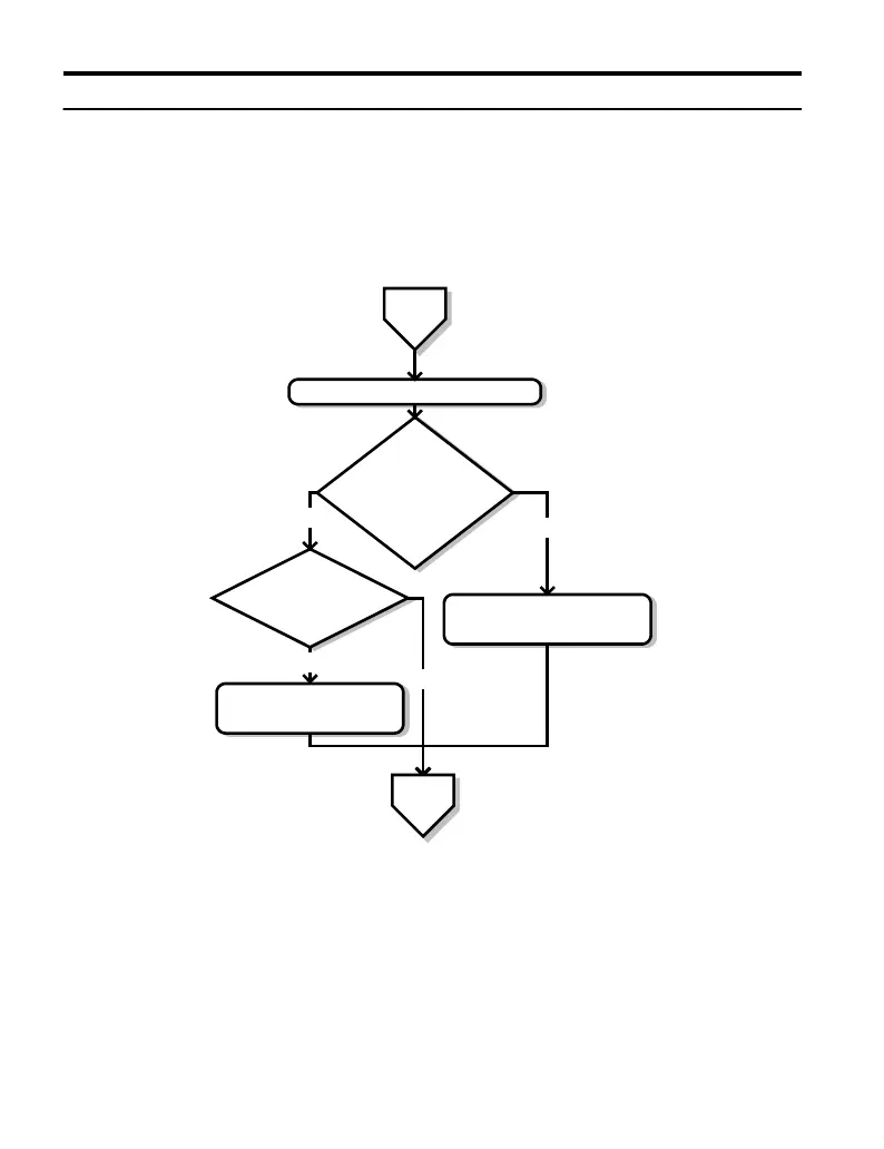
Figure 4.5, Flowchart A1, describes simple motor setup for V/f control. V/f Motor Control
is suited for the most basic applications such as fans or pumps. This procedure illustrates using
Energy Savings and Speed Estimation Speed Search. V/f control can be used where rotational
auto-tuning cannot be performed.
From
Flowchart
A
Set or verify the V/f pattern settings E1-oo.
Energy Savings
(b8-01=1)
or
Speed Estimation
Speed Search (b3-24=1)
enabled ?
Is the motor cable
longer than 50 m?
Perform Rotational Auto-Tuning
for V/f Control
(T1-01 = 3)
NO
YES
Perform Stationary Auto-Tuning for
terminal resistance (T1-01 = 2)
YES
NO
Return to
Flowchart
A
Figure 4.5 Simple Motor Setup with Energy Savings or Speed Search Using V/f Mode
4.3 Start-up Flowcharts
92
YASKAWA ELECTRIC TOEP C710606 47A YASKAWA AC Drive – V1000 Quick Start Guide

Table of Contents

Other manuals for YASKAWA V1000

Questions and Answers:

Question and Answer IconNeed help?

Do you have a question about the YASKAWA V1000 and is the answer not in the manual?

YASKAWA V1000 Specifications

General IconGeneral
Input Voltage3-Phase 200-240VAC, 3-Phase 380-480VAC
Output Voltage3-Phase 200-240VAC, 3-Phase 380-480VAC
Output Frequency0-400 Hz
Control MethodV/f control
Overload Capacity150% for 60 seconds
Protection FunctionsOvercurrent, Overvoltage, Undervoltage, Overheating, Short Circuit, Ground Fault
Communication OptionsModbus RTU
Ambient Temperature-10 to +50°C (14 to 122°F)
Storage Temperature-20°C to +65°C (-4°F to 149°F)
Humidity95% (non-condensing)
Cooling MethodForced Air Cooling
EnclosureIP20

Related product manuals