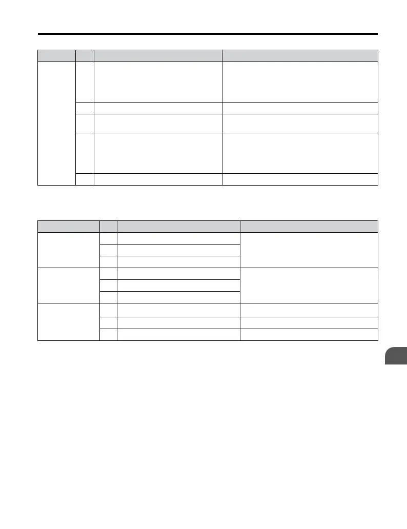
Type No. Terminal Name (Function) Function (Signal Level) Default Setting
Main
Frequency
Reference
Input
RP
Multi-function pulse train input (frequency
reference)
Response frequency: 0.5 to 32 kHz
(Duty Cycle: 30 to 70%)
(High level voltage: 3.5 to 13.2 Vdc)
(Low level voltage: 0.0 to 0.8 Vdc)
(input impedance: 3 kΩ)
+V Analog input power supply +10.5 Vdc (max allowable current 20 mA)
A1
Multi-function analog input 1 (frequency
reference)
Input voltage 0 to +10 Vdc (20 kΩ) resolution 1/1000
A2
Multi-function analog input 2 (frequency
reference)
Input voltage or input current (Selected by DIP switch
S1 and H3-09) 0 to +10 Vdc (20 kΩ),
Resolution: 1/1000
4 to 20 mA (250 Ω) or 0 to 20 mA (250 Ω),
Resolution: 1/500
AC Frequency reference common 0 Vdc
n
Output Terminals
Table 3.7 Control Circuit Output Terminals
Type No. Terminal Name (Function) Function (Signal Level) Default Setting
Multi-Function
Digital Output
<1>
MA N.O. (fault)
Digital output
30 Vdc, 10 mA to 1 A; 250 Vac, 10 mA to 1 A
Minimum load: 5 Vdc, 10 mA (reference value)
MB N.C. output (fault)
MC Digital output common
Multi-Function
Photocoupler
Output
P1 Photocoupler output 1 (During run)
Photocoupler output 48 Vdc, 2 to 50 mA
<2>
P2 Photocoupler output 2 (Frequency agree)
PC Photocoupler output common
Monitor Output
MP Pulse train output (Output frequency)
32 kHz (max)
<3>
<4>
AM Analog monitor output 0 to 10 Vdc (2 mA or less) Resolution: 1/1000
AC Monitor common 0 V
<1> Do not assign functions to digital relay outputs that involve frequent switching. This may shorten relay
performance life. Switching life is estimated at 200,000 times (assumes 1 A, resistive load).
<2> Connect a suppression diode as shown in Figure 3.14 when driving a reactive load such as a relay coil. Ensure
the diode rating is greater than the circuit voltage.
<3> When set for sourcing. +5 V/1.5 kΩ or higher, +8 V/3.5 kΩ or higher, +10 V/10 kΩ or higher.
<4> When set for sinking, the external power supply should be +12 Vdc, ±5% with 16 mA or less.
3.5 Control Circuit Wiring
YASKAWA ELECTRIC TOEP C710606 47A YASKAWA AC Drive – V1000 Quick Start Guide
67
3
Electrical Installation