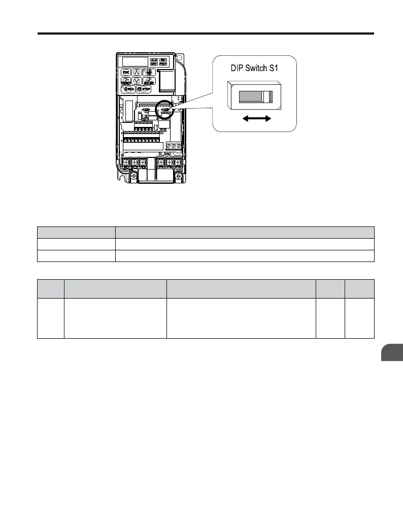
Figure 3.22 DIP Switch S1
Table 3.13 DIP Switch S1 Settings
Setting Value Description
V (left position) Voltage input (0 to 10 V)
I (right position) Current input (4 to 20 mA or 0 to 20 mA): default setting
Table 3.14 Parameter H3-09 Details
No. Parameter Name Description
Setting
Range
Default
Setting
H3-09
Frequency ref. (current)
terminal A2 signal level selection
Selects the signal level for terminal A2.
0: 0 to +10 V, unipolar input (with lower limit)
1: 0 to +10 V, bipolar input (no lower limit)
2: 4 to 20 mA
3: 0 to 20 mA
0 to 3 2
3.7 Main Frequency Reference
YASKAWA ELECTRIC TOEP C710606 47A YASKAWA AC Drive – V1000 Quick Start Guide
77
3
Electrical Installation