Do you have a question about the YASKAWA YR-UP6-A00 and is the answer not in the manual?
Provides essential tips for safe operation, personnel familiarization, and hazard avoidance.
Provides suggestions for safe installation, supplementing regulations and emphasizing qualified personnel.
Offers programming tips, warns against modifications, and stresses the importance of backups.
Provides operational tips, emphasizes trained personnel, and details safety checks before system use.
Offers maintenance tips, emphasizing reading procedures, safety checks, and proper parts usage.
Describes safe transport using crane or forklift, emphasizing authorized personnel.
Emphasizes installing safety guards to prevent accidents and equipment damage.
Details foundation requirements and mounting procedures for the baseplate.
Details connecting power and signal cables between manipulator base and XRC.
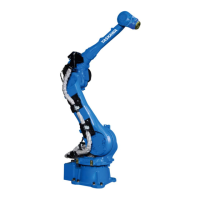
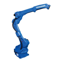
Presents operational data, motion range, speed, moment, mass, and ambient conditions.
Specifies allowable wrist load and force limits for R-, B-, T-Axes, considering inertia.
Describes conditions for attaching peripheral equipment to U-axis, including load and position.
Details periodical inspections by operation type and charge to ensure function and safety.
Provides critical safety warnings before performing maintenance or inspection.
Explains XRC security system protecting modes, detailing operation, editing, and management modes.
Covers system setup: home position calibration, specified points, and controller clock settings.
Details security system protecting XRC modes, allowing operation and modification based on operator clearance and user IDs.
Describes three security modes: Operation, Editing, and Management, each requiring specific user IDs and access levels.
Details User ID requirements and procedure for changing a User ID in Editing or Management Mode.
Explains calibrating home position and encoder zero position after component changes or deviation.
Details purpose of position check and setting specified points for absolute data check.
Explains function to prevent interference between manipulators or devices, setting cubic and axis areas.
Explains purpose of operation origin point and procedures for displaying, registering, and clearing it.
Crucial for robot application; details registering tool files, including number of files and coordinate data registration.
Details registering tool files, including number of files and coordinate data registration.
Explains registering tool pose data (flange and tool coordinates) for accurate TCP operation.
Describes tool calibration for accurate interpolation, defining dimensional info and tool center point.
Explains function to register tool load and center of gravity, and details measurement process.
Defines user coordinates by three points (ORG, XX, XY) and how to register them in a file.
Defines user coordinates by three taught points (ORG, XX, XY) and explains how to register them in a user coordinate file.
Details teaching ORG, XX, XY points for user coordinates, registering taught positions.
Introduces ARM control for enhanced path accuracy and cycle time by calculating inertia and load.
Explains setting robot setup conditions and tool load info in ARM CONTROL display, stressing accuracy.
Details necessary conditions for ARM control: installation angle, S-head, U-arm payload.
Stresses setting tool load info correctly for accurate shock detection, longevity, and alarm prevention.
Explains tool load info components: weight, center of gravity, moment of inertia, registered in tool file.
Explains registering tool load information in tool file, covering tool list, coordinate display, and inputting values.
Describes shock detection function to stop manipulator instantly on collision without external sensors.
Explains setting shock detection levels and sensitivity to improve performance and prevent mis-detection.
Details shock detection level file, condition numbers, and setting detection levels for play/teach modes.
Describes setting shock detection level, recommending values higher than max disturbance force.
Explains setting tool load information in tool file for accurate shock detection, longevity, and alarm prevention.
Explains customizing functions allocated to number keys to reduce key operations and teaching time.
Lists controller specifications: configuration, cooling, power supply, and I/O.
Describes XRC configuration: unit and circuit board arrangements for different models.
Describes the power supply unit, its components, and its function.
Details Servopack composition, boards, converters, amplifiers, with configuration tables.
Provides detailed signal assignments for general I/O: Arc Welding, Handling, Spot Welding, General.
Outlines regular inspections for XRC controller, fans, E-stop, deadman switch, and battery.
Details XRC checks: door closure, seal integrity, and interior cleanliness.
Details confirming servo power OFF by pressing E-stop buttons on playback panel and pendant.
Confirms operation of the three-position deadman switch on the programming pendant.
Provides safety warnings before opening XRC doors and performing part replacements.
Describes replacing Servopacks (integrated/separated types) and listing cable connections.
Classifies alarms by level (major/minor) and describes servo power interruption for major alarms.
Explains how alarms are displayed and procedures for releasing minor and major alarms.
Provides detailed alarm numbers, messages, causes, and remedies for troubleshooting.
Provides a list of errors, messages, and contents, explaining differences from alarms.
| Axes | 6 |
|---|---|
| Payload | 6 kg |
| Repeatability | ±0.03 mm |
| Type | Articulated |
| Model | YR-UP6-A00 |
| Manufacturer | YASKAWA |
| Weight | 130 kg |
| Robot Weight | 130 kg |
| Mounting | Floor, Wall, Ceiling |