App-15
IM DL850E-01EN
Appendix
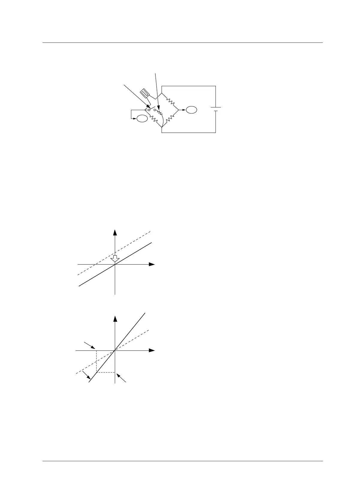
• When correcting the gain on the positive side
Bridge+
Bridge–
In+
In–
Shunt resistor, when
correcting the positive side
Bridge
voltage
120 Ω
120 Ω
120 Ω
Shunt calibration relay circuit
(Built into the strain module.
Turns on and off automatically
when shunt calibration is
executed.)
Shunt Calibration Procedure
1. Calculate the strain value (μSTR) that corresponds to the shunt resistor you will use. For the calculation
procedure, see “Calculating the Shunt Resistance” in the next section.
2. Execute balancing without applying a load to the strain gauge, and correct the zero point.
3. Execute shunt calibration, and correct the gain.
To execute shunt calibration, in the CH menu, select Linear Scale, Mode, and then Shunt. Usually
, the
negative gain is corrected. However, if you are correcting the positive gain, change the position of the shunt
resistor as shown in the above figure.
Strain input
Strain
• Balance
Before execution
After execution
The zero point is corrected
when balancing is executed.
Strain
P2:Y
P2:X
Strain input
• Shunt calibration
Current measured
value
*
Before execution
After execution.
The gain is corrected.
* Obtained automatically when shunt calibration is performed
In the setup menu, set the strain value
corresponding to the shunt resistor to P2:Y.
 Loading...
