Setting the Delay (Delay Setup)
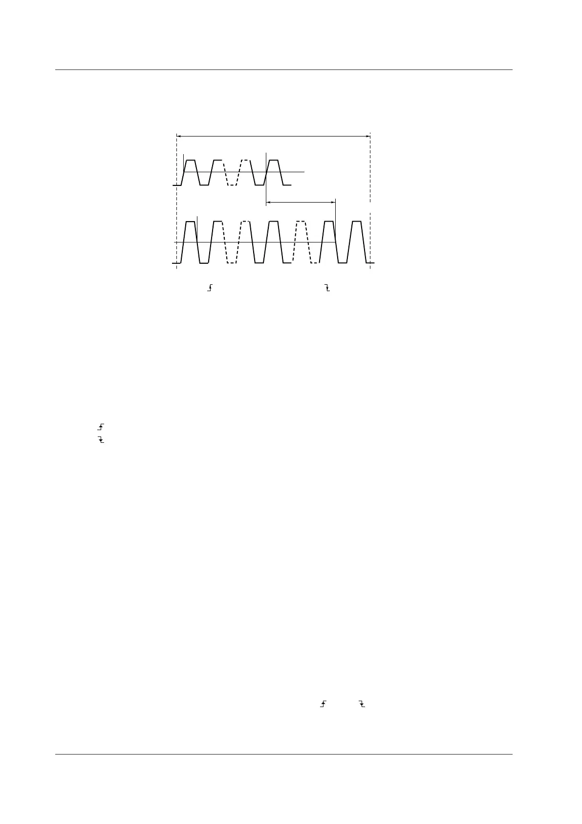
The time difference between traces or the time difference from the trigger point to a rising or falling edge is called
the delay between channels.
Reference waveform
(Reference)
Source waveform
(Measure)
Count 1
Count N1
Count N2
Count 1
Delay between channels
• Polarity:
• Edge Count:
Reference waveform settings Source waveform settings
Period
• Polarity:
• Edge Count:
Mesial line
(rising)
N1 (an integer
between 1 and 9)
(falling)
N1 (an integer
between 1 and 9)
• Mode
Select a delay measurement mode.
• OFF: Delay measurement is not performed.
• Time: The delay between channels is displayed as a time.
• Degree: The delay between channels is displayed as an angle.
• Polarity
Select the slope of the edge you want to detect.
•
: Rising
•
: Falling
• Edge Count
Sets which edge counted from the start point (T Range1) of the measurement time period to use as a
detected point (measured point).
Selectable range: 1 to 9
• Reference
Select whether to use a trace or trigger as the reference for the reference waveform.
• Trace: A
trace is used.
• Trigger: A trigger is used.
• Reference Waveform (Reference Trace)
When Reference is set to Trace, set the reference waveform.
• Trace: Select a reference waveform. CH1 to CH16,
1
16chVOLT,
2
16chTEMP/VOLT,
2
CAN,
3
LIN,
3
Math1 to
Math8
1 You can select the channel of an installed module.
2 When a 16-CH voltage input module or 16-CH temperature/voltage input module is installed. After you
select 16chVOL
T or 16chTEMP/VOLT, select a sub channel.
3 On the DL850EV when a CAN bus monitor module or CAN & LIN bus monitor module is installed. After
you select CAN or LIN, select a sub channel. You cannot select waveforms whose data type (V
alue
Type) is set to Logic.
• Polarity: Select the slope of the edge you want to detect (
: rising, : falling).
• Edge Count: Sets which edge counted from the start point (T Range1) of the measurement time period to
use as a detected point (reference point). Selectable range: 1 to 9
10 Automated Measurement of Waveform Parameters
 Loading...
