2-39
IM DL850E-01EN
Logic Measurement
For logic measurement, the items that have to be set for each input signal (CH1 to CH16) include vertical scales,
the logic bit settings, the logic bit mapping, the zoom method, and trace settings.
You can measure logic signals by connecting a logic probe to the 720230 (LOGIC) logic module.
For information about how to connect logic probes, see section 3.10 in the Getting Started Guide, IM DL850E-
03EN.
Waveform Display (Display)
Select whether to display each channel’s input signal waveform.
• ON: Displays the waveform
• OFF: Does not display the waveform
Labels (Label)
Waveform Vertical Position (Vertical POSITION knob)
Logic Bit Settings (Logic Bit Setup)
Bit Display (Display)
You can set whether to display the waveform of each bit.
Bit1 to Bit8, All Bits On, All Bits Off
Bit Name (Bit Name)
You can assign labels to bits using up to sixteen characters.
Depending on the display and zoom formats, label names may not appear when the waveform display is
narrow.
Chattering Elimination (Chatter Elimination)
For each bit, you can set whether to eliminate chattering. To eliminate chattering, select an elimination time.
OFF, 5msec, 10msec, 20msec, 50msec, 100msec
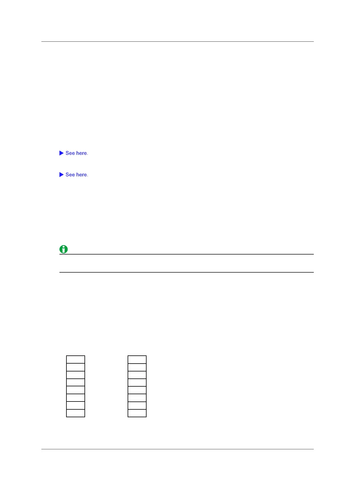
Bit Mapping (Bit Mapping)
• Fixed: Spaces are allocated for bits that are turned off.
• Auto: Spaces are not allocated for bits that are turned off. Only the bits that are turned on are displayed. The
bits are displayed in order from the top.
A1
A3
A2
A4
A5
A6
A8
A1
A3
A2
A4
A5
A6
A8
Fixed (When bit 7 is off)
Auto (When bit 7 is off)
2 Vertical Axis
 Loading...
