2-42
IM DL850E-01EN
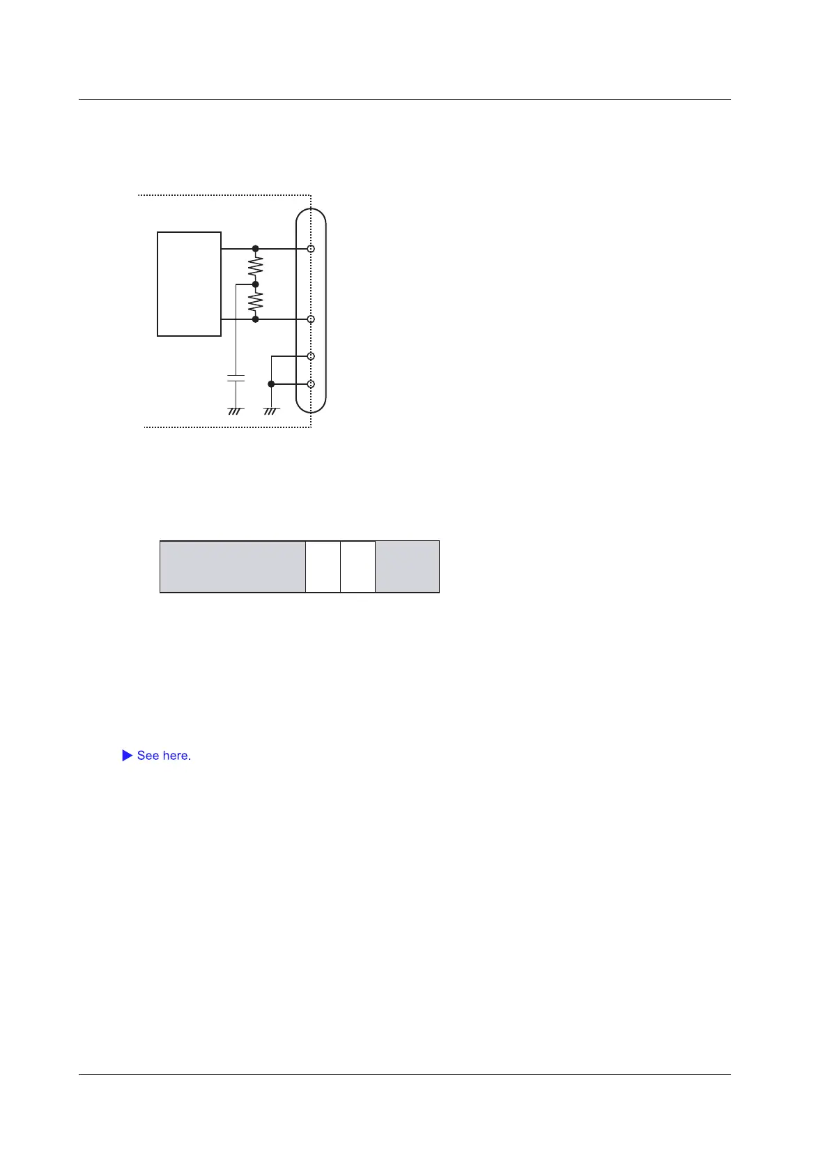
• Terminator (Terminator)
ON: The 120 Ω terminator between CAN_H and CAN_L on the CAN bus line is turned on.
OFF: The terminator between CAN_H and CAN_L on the CAN bus line is turned off.
CAN I/F
CAN TRANSCEIVER
CAN_H
60 Ω
7
2
3
6
60 Ω
CAN_H
CAN_L CAN_L
GND
GND
0.1 μF
CAN Data Extraction Conditions
Set the extraction conditions for the CAN data that is in the data field. You can configure the settings for each
sub channel. There are up to 60 sub channels for each port.
When the data field contains two units of data
bit
64 56 48 40 32 24 16 8 0
CH15_2 CH15_1
• Start Bit = 0, Bit Count = 16bit → 2-byte integer (CH15_1)
• Start Bit = 32, Bit Count = 32bit → 4-byte integer (CH15_2)
4-byte real numbers can be extracted by modules whose firmware version
is 1.20 and later.
Input (Input)
ON: The data is monitored.
OFF: The data is not monitored or displayed.
Labels (Label)
Message Format
Select the message format of the collected data frames.
STD: Standard format
XTD: Extended format
ID (Hex)
Set the message ID of the collected data frames.
Standard format (11 bits): 0x000 to 0x7ff
Extended format (29 bits): 0x00000000 to 0x1fffffff
2 Vertical Axis
 Loading...
