49
Printer Setup and Operation
Print Engine Installation
8/23/12 P1051584-002
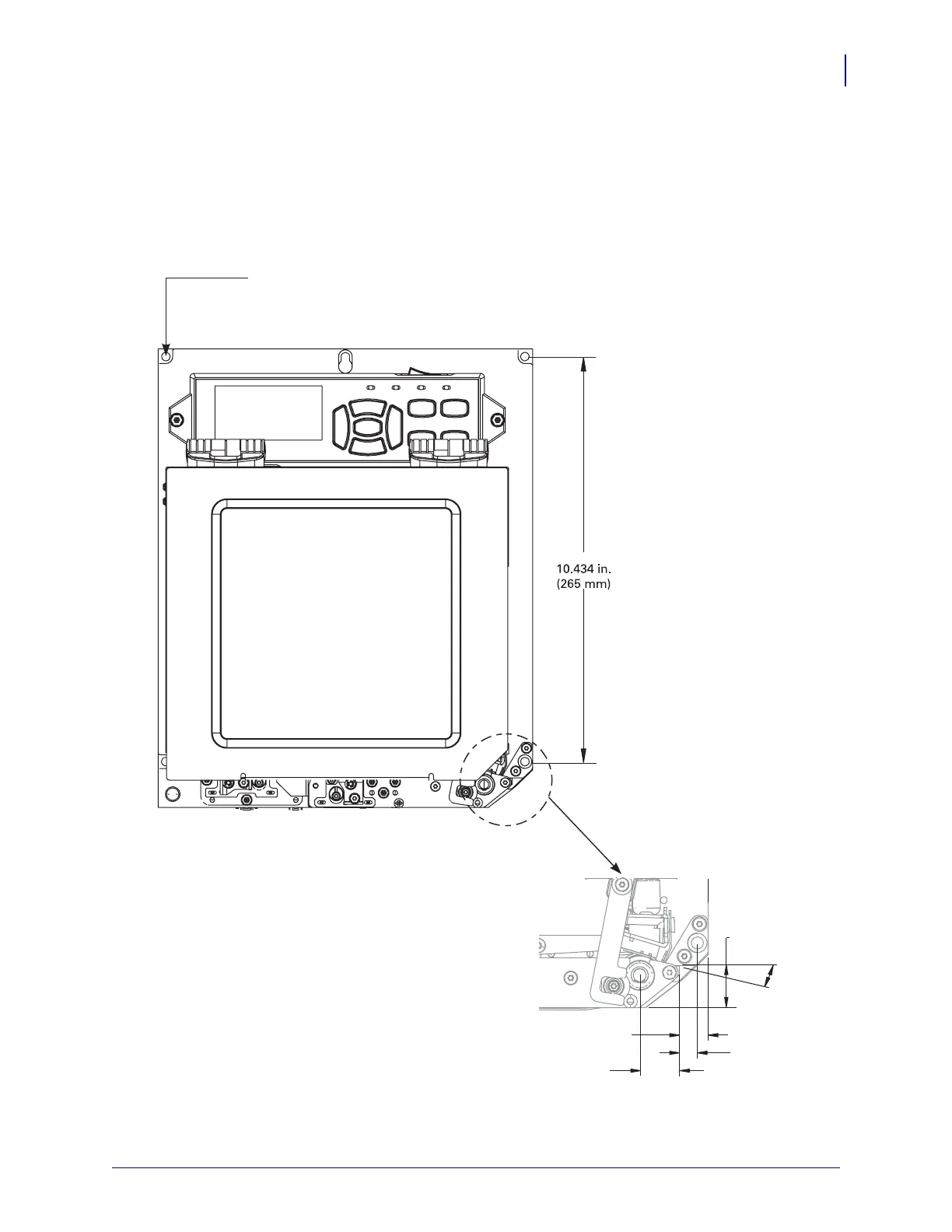
Dimensions and Clearance Needs
This section shows measurements relevant when installing the ZE500 print engine in an
applicator.
Front View (Right-Hand Print Engine Shown)
5 mounting screws
- 0.218 in. (5.5 mm) through
- counterbore 0.350 in. x 0.197 in. (8.9 x 5 mm) deep
- socket head cap screw (M5)
18°
0.669 in.
(17 mm)
0.532 in
(13.50 mm)
0.335 in.
(8.50 mm)
0.721 in
(18.31 mm)