Safety measures S88 / OPMI Lumera T
Version 8.0
Page 46 G-30-1682-en
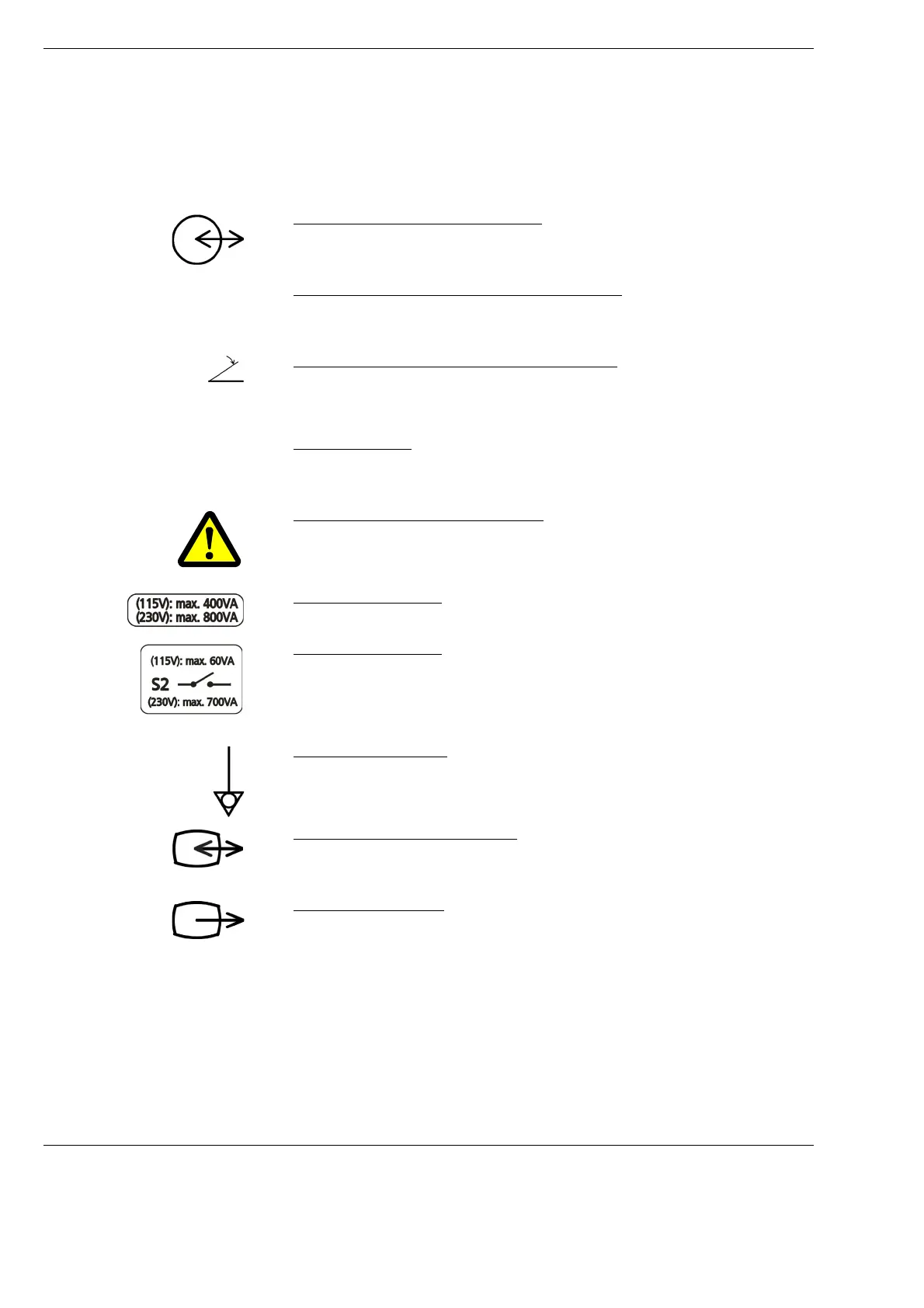
Labels on the connector panel of the S88 floor stand
1 Symbol for signal input and output
Identification mark of the remote connection
2 Indication of the maximum switching capacity
Only devices with a maximum switching capacity of 24V/0.5A may be
connected to this remote connection.
3 "Connector of wired foot control panel" label
4 Power switch S2
For switching the system on and off. When the system has been switched
on, the green lamp in the switch is lit.
5 Power output socket warning label
Only connect devices with the correct electrical ratings.
6 Power output socket
with permissible electrical values for connected devices.
7 Power output socket
with permissible electrical values for connected devices.
The current in this power output is switched on/off using power switch S2.
8 Potential equalization
For connecting the system to the potential equalization system.
9 Signal output and input symbol
Symbol for the remote connection (1) for the optional model of the
connection panel for an ocular fundus image system
10 Signal output symbol
Symbol for the remove connection for an ocular fundus image system,
optional model of the connection panel for an ocular fundus image system
max. 24V / 0.5A
S2
 Loading...