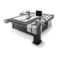
Setting up the control panel/workstation
16
4 PC
5 Workstation power supply (connector control)
6 Workstation/operating unit
7 Control unit cable
8 Operating unit underside
9 Emergency stop control device cable
10 Electronics unit
11 Control unit cable light curtain S16
12 Signal light cable (Variofac 2, optional)
13 Earthing cable
14 Signal light cable (ACS_IO_BOARD_ENA) optional, cutter with tandem
A PC and cutter side support, right:
a) Unplug the LAN cable and remove. Replace the cable with the longer LAN cable.
b) Unplug and remove the video signal cable (ICC camera). Replace this cable with the longer
video signal cable.
B Operating unit:
a) Unplug the operating unit cable and remove from the control panel/workstation. Replace this
cable with the longer operating unit cable.
C Electronics unit:
a) Signal light (optional): pull out the stranded wires of the cable from the Varioface 2 and remove
the cable from the cutter. Attach the extension.
b) Unplug the operating unit cable (ACS_BF_BOARD S16) and remove from the cutter. Replace
this cable with the longer cable.
D Workstation:
a) Unplug the power supply. An extension is available for this cable.
E Cutter side support, right
a) Unplug the earthing cable.
F Control panel/workstation:
a) Remove the earthing cable. Replace this cable with the longer cable.
 Loading...