8 9
1
1
OPTIONAL 3M™ATTEST™ AUTO-READER390G WEBAPP
Web BrowserRequirements
The Web Interface is designed to be viewed in Internet Explorer 8.0or higher. Earlier
versions of Internet Explorer or other browsers may result in some web pages being
displayed in a less-than-optimum manner. For best results, switching to Internet Explorer
8.0or higher is recommended. For full functionality, the use of an HTML5compliant
browser with JavaScript enabled isrecommended.
Connecting to the 3M™Attest™ Auto-reader390G WebApp
To use the 3M™Attest™ Auto-reader390G Web App, the 3M™Attest™ 390G
Auto-reader must be connected to the facility network using the supplied Ethernet
cable. Consult with your facility IT personnel for assistance with network connectivity.
Users may connect to the 3M™Attest™ Auto-reader390G Web App using a URL based
upon either the 3M™Attest™ Auto-reader390G serial number or the IP Address. To
view the 3M™Attest™ Auto-reader390G Web App from a wireless device such as a
mobile hand-held device or a computer on a sub-net different from that to which the
3M™Attest™ Auto-reader390G is connected, use the IP AddressURL.
Note: To access the 3M™Attest™ Auto-reader390G Web App within a secure network,
the PC or mobile device must have access to the secure network; options include
connecting via a network Ethernet cable, signing in to the facility’s wireless network, or
connecting via a virtual private network(VPN).
A. Serial numberURL
1. Connect the supplied Ethernet cable from the 3M™Attest™ Auto-reader390G to an
Ethernetjack.
2. Depress the
button once to display the 3M™Attest™ Auto-reader390G 6-digit
serial number on the left side of the top row of text on the LCDdisplay.
3. Enter http://attestxxxxxx where xxxxxx represents the unit’s serial number (e.g., http://
attest401008) from Step 2in PC web browser address bar and pressGo.
4. 3M™Attest™ Auto-reader390G Web App Status page will display on PC. For future
ease of use, add this page to your web browser“Favorites.”
B. IP AddressURL
The 3M™Attest™ Auto-reader390G Web App may also be accessed using either a
dynamic or static IPaddress.
1. Dynamic IPAddress
A dynamic IP address is assigned when the Ethernet cable is connected from the
3M™Attest™ Auto-reader390G to a live Ethernetjack.
Press and release the
button twice to display the 3M™Attest™ Auto-reader390G’s
dynamic IP address. Enter http://IPaddress (e.g. http://123.45.678.90) in the web browser
address bar of the PC or mobile hand-held device and press Enter. The 3M™Attest™
Auto-reader390G Web App Status page willdisplay.
2. Static IPaddress
Some facility IT personnel may require devices connecting to the network to use a Static
IP address. If this is the case at your facility, contact the IT department to request a Static
IPaddress.
Record the static IP address provided by your facility IT department here: ___________.
You may wish to label the Ethernet jack with the assigned address. Enter
http://StaticIPaddress (e.g. http://111.22.333.44) in the web browser address bar on your
PC or mobile hand-held device and press Enter. The 3M™Attest™ Auto-reader390G
Web App Status page willdisplay.
About the 3M™Attest™ Auto-reader390G Web AppPages
The 3M™Attest™ Auto-reader390G Web App includes fourpages:
a) Statuspage
Status
History
3M™ Attest™ Auto-reader 390G
AT TE ST 1294 AT TE ST 1294
1 2 3 4 5
+ – 85 240
6 7 8 9 10
SN
100122
2012-10-31 12:32
1. User-entered nickname(optional)
2. Well Configuration (1-5and6-10)
3. WellNumber
4. BIResult/Remaining IncubationTime
5. Date andTime
6. 3M™Attest™ Auto-reader390G SerialNumber
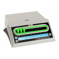
The Status page provides a real-time representation of the 3M™Attest™
Auto-reader390G LCD panel display. The current date and time and 3M™Attest™
Auto-reader390G serial number are also indicated on this page. From this page, the user
may navigateto:
•
the History page by clicking on History on the left of thescreen.
•
the Results Detail page by clicking on the well number of an occupied well (i.e., a well
that currently has an incubating BI). Clicking on an unoccupied well takes the user to
the Historypage.
b) Results Detailpage
3M™ Attest™ Auto-reader 390G Results Detail
Status
History
Print
Result
Start Time
Well# and Configuration
390G Serial Number
Control?
BI Lot#
Load#
Sterilizer#
Technician
–
2012-10-29 11:08:04
#3 1294
100122
This page provides an individual record for an incubated BI. For complete documentation,
the user may print a hard copy and/or save the record as an electronicfile.
Note 1: The top four rows (highlighted in green) are populated automatically by the
3M™Attest™ Auto-reader390G and cannot be changed by the user. The remaining rows
are completed by the user to satisfy the documentation requirements of theirfacility.
Note 2: The Results Detail page refreshes less frequently that the Status page. Until the BI
result is available, the Results Detail page displays remaining minutes of incubation in the
resultsfield.
TROUBLESHOOTINGGUIDE
In the event of an error code, unplug the 3M™Attest™ Auto-reader390G and plug it back in to initiate the self-diagnostic test. If error code re-occurs, call for repair orreplacement.
The LCD display panel will indicate detected malfunctions by displaying a caution or error code under affected BI wells. The audible alarm, if active, sounds and the LCD display
backlight flashes to alert the user to all caution (except C1) and error codes. The alarm and backlight can be silenced and extinguished, respectively, by pressing the Buzzer Alarm OFF
button
. Note that disabling the audible alarm does not disable the flashing LCD display backlight. Refer to thefollowing:
Code/Issue Problem Solution
C1
Unit Warm-upCaution
Incubation block not at temperature.
Allow a 30minute warm-up after 3M™Attest™ Auto-reader390G is plugged in. (Note: 3M™Attest™
Rapid Readout BI readings are disabled until incubator block reaches 37ºC +/- 2ºC).
C2
BI Removed from WellCaution
3M™Attest™ Rapid Readout BI has been removed before
incubation is complete.
Replace 3M™Attest™ Rapid Readout BI in proper well within 10seconds to prevent loss of collected
data.
C4 Ambient Light Caution Move 3M™Attest™ Auto-reader390G to reduced ambient light conditions.
E1
Temperature ControlError
This error will occur if system is no longer able to control
the temperature of the incubator block (37ºC +/- 2ºC).
Unplug the unit and plug it back in to clearerror.
If error doesn’t clear, call for repair or replacement.
E3
MemoryError
3M™Attest™ Auto-reader390G unable to save/read data
from memory.
Unplug the unit and plug it back in to clearerror.
If error doesn’t clear, call for repair or replacement.
E7
CommunicationsError
This error will occur if internal communications have failed.
Call for repair or replacement.
E8
LEDError
This error occurs for a specific well if the system detects
that a UV LED or Optics Detection circuit is not working.
Unplug the unit and plug it back in to clearerror.
If error doesn’t clear, call for repair or replacement. Do not use affected incubation well.
E11
BI Inserted IncorrectlyError
Incubation time remaining will not display and fluorescent
readings are not taken.
Ensure BI is designed to be incubated and read in the 3M™Attest™ Auto-reader390G.
Ensure BI is fully inserted into incubation well.
E12
Power FailureError
Power to Auto-reader was off for too long to provide valid
result for affected BI(s).
Ensure power supply connection to Auto-reader is secure.
E14
Ambient Light Error (occupiedwell)
Fluorescent result will not display.
Rely on optional visual pH color change result for BI in affected well. Move 3M™Attest™
Auto-reader390G to reduced ambient light conditions to avoid future occurrences.
Other Unwanted alarm sounds when positive BI detected. Disable alarm; refer to 3M™Attest™ Auto-reader390G Configuration section for instructions.
Other
AlarmSounds
3M™Attest™ Rapid Readout Biological Indicator has been
removed from incubation/reader well prematurely.
Replace 3M™Attest™ Rapid Readout Biological Indicator in incubation/reader well within 10seconds
to prevent loss of data collected.
Other LCD panel does not display properly. Unplug the unit and plug it back in. If problem persists call for repair or replacement.
Other
Negative ControlVial
BI not properly activated/ media did not contact spore strip.
Ensure BI cap is closed, and glass ampoule is crushed. Tap BI until media flows to and wets spore strip
at bottom of BI.
Other
Negative ControlVial
Control vial was sterilized.
Check process indicator on BI label. Use a non-sterilized vial as a control.
Other
Unexplained PositiveBI
Adhesive residue on vial.
Do not place tape or labels onvial.
Other
Unexplained PositiveBI
Test vial is absorbing fluorescent residue from a chemical
indicator or tape.
Place the vial so it does not come in direct contact with chemical indicators or tape.
Other
3M™Attest™ Auto-reader390G will not enter
Configurationmode.
Pushbutton Configuration may be disabled on
3M™Attest™ Auto-reader390G Web App.
On 3M™Attest™ Auto-reader390G Web App Configuration Page, go to Pushbutton Configuration and
select the Enable radio button. Save changes to begin using new setting.
Other
3M™Attest™ Auto-reader390G LCD display flashes
and asterisks (***) and/or E11and/or C4codes appear on
display below unoccupied incubation wells.
Move 3M™Attest™ Auto-reader390G away from sunlight or sources of incandescent light.
Rendered on 9/12/2013 10:34:26 AM
 Loading...