ACS550 User’s Manual 181
Parameters
8120 INTERLOCKS
Defines operation of the Interlock function. When the Interlock function is enabled:
• An interlock is active when its command signal is absent.
• An interlock is inactive when its command signal is present.
• The ACS550 will not start if a start command occurs when the speed regulated motor’s interlock is active – the
control panel displays an alarm (2015,
PFC I LOCK).
Wire each Interlock circuit as follows:
• Wire a contact of the motor’s On/Off switch to the Interlock circuit – the drive’s PFC logic can then recognize that
the motor is switched off and start the next available motor.
• Wire a contact of the motor thermal relay (or other protective device in the motor circuit) to the Interlock input – the
drive’s PFC logic can then recognize that a motor fault is activated and stop the motor.
0 =
NOT SEL – Disables the Interlock function. All digital inputs are available for other purposes.
• Requires 8118
AUTOCHNG INTERV = 0 (The Autochange function must be disabled if Interlock function is disabled.)
1 =
DI1 – Enables the Interlock function and assigns a digital input (starting with DI1) to the interlock signal for each
PFC relay. These assignments are defined in the following table and depend on:
• the number of PFC relays [number of parameters 1401…1403 and 1410…1412 with value = 31 (
PFC)]
• the Autochange function status (disabled if 8118
AUTOCHNG INTERV = 0, and otherwise enabled).
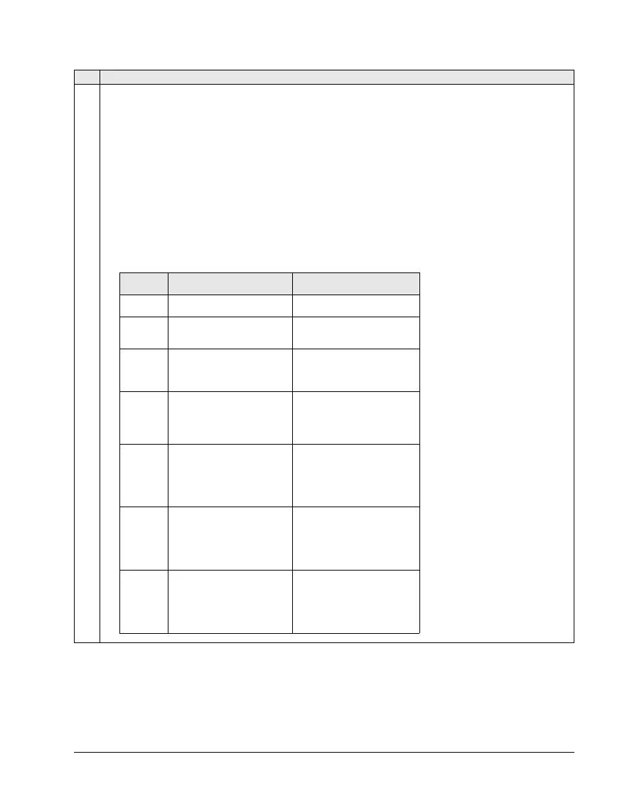
Code Description
No. PFC
relays
Autochange disabled
(P 8118)
Autochange enabled
(P 8118)
0
DI1: Speed Reg Motor
DI2…DI6: Free
Not allowed
1
DI1: Speed Reg Motor
DI2: First PFC Relay
DI3…DI6: Free
DI1: First PFC Relay
DI2…DI6: Free
2
DI1: Speed Reg Motor
DI2: First PFC Relay
DI3: Second PFC Relay
DI4…DI6: Free
DI1: First PFC Relay
DI2: Second PFC Relay
DI3…DI6: Free
3
DI1: Speed Reg Motor
DI2: First PFC Relay
DI3: Second PFC Relay
DI4: Third PFC Relay
DI5…DI6: Free
DI1: First PFC Relay
DI2: Second PFC Relay
DI3: Third PFC Relay
DI4…DI6: Free
4
DI1: Speed Reg Motor
DI2: First PFC Relay
DI3: Second PFC Relay
DI4: Third PFC Relay
DI5: Fourth PFC Relay
DI6: Free
DI1: First PFC Relay
DI2: Second PFC Relay
DI3: Third PFC Relay
DI4: Fourth PFC Relay
DI5…DI6: Free
5
DI1: Speed Reg Motor
DI2: First PFC Relay
DI3: Second PFC Relay
DI4: Third PFC Relay
DI5: Fourth PFC Relay
DI6: Fifth PFC Relay
DI1: First PFC Relay
DI2: Second PFC Relay
DI3: Third PFC Relay
DI4: Fourth PFC Relay
DI5: Fifth PFC Relay
DI6: Free
6 Not allowed
DI1: First PFC Relay
DI2: Second PFC Relay
DI3: Third PFC Relay
DI4: Fourth PFC Relay
DI5: Fifth PFC Relay
DI6: Sixth PFC Relay