182 ACS550 User’s Manual
Parameters
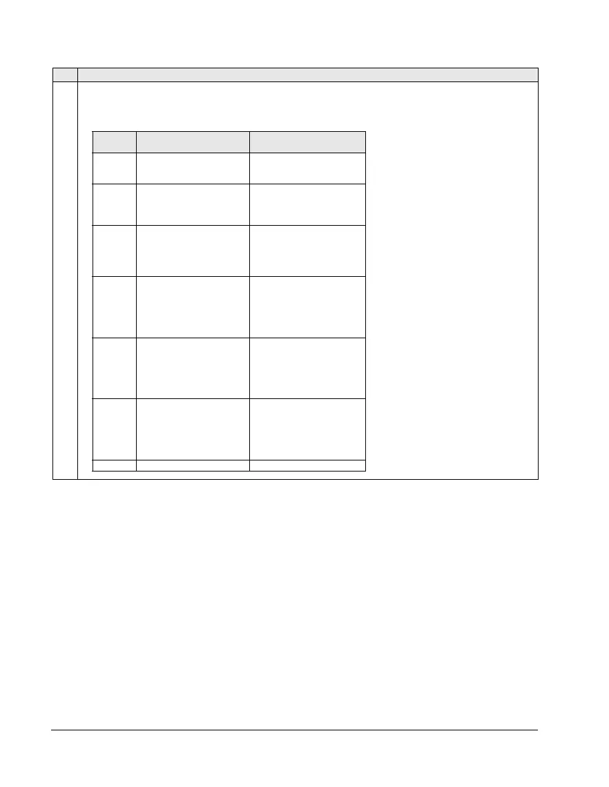
2 = DI2 – Enables the Interlock function and assigns a digital input (starting with DI2) to the interlock signal for each
PFC relay. These assignments are defined in the following table and depend on:
• the number of PFC relays [number of parameters 1401…1403 and 1410…1412 with value = 31 (
PFC)]
• the Autochange function status (disabled if 8118
AUTOCHNG INTERV = 0, and otherwise enabled).
Code Description
No. PFC
relays
Autochange disabled
(P 8118)
Autochange enabled
(P 8118)
0
DI1: Free
DI2: Speed Reg Motor
DI3…DI6: Free
Not allowed
1
DI1: Free
DI2: Speed Reg Motor
DI3: First PFC Relay
DI4…DI6: Free
DI1: Free
DI2: First PFC Relay
DI3…DI6: Free
2
DI1: Free
DI2: Speed Reg Motor
DI3: First PFC Relay
DI4: Second PFC Relay
DI5…DI6: Free
DI1: Free
DI2: First PFC Relay
DI3: Second PFC Relay
DI4…DI6: Free
3
DI1: Free
DI2: Speed Reg Motor
DI3: First PFC Relay
DI4: Second PFC Relay
DI5: Third PFC Relay
DI6: Free
DI1: Free
DI2: First PFC Relay
DI3: Second PFC Relay
DI4: Third PFC Relay
DI5…DI6: Free
4
DI1: Free
DI2: Speed Reg Motor
DI3: First PFC Relay
DI4: Second PFC Relay
DI5: Third PFC Relay
DI6: Fourth PFC Relay
DI1: Free
DI2: First PFC Relay
DI3: Second PFC Relay
DI4: Third PFC Relay
DI5: Fourth PFC Relay
DI6: Free
5 Not allowed
DI1: Free
DI2: First PFC Relay
DI3: Second PFC Relay
DI4: Third PFC Relay
DI5: Fourth PFC Relay
DI6: Fifth PFC Relay
6 Not allowed Not allowed