68 ACS550 User’s Manual
Control panels
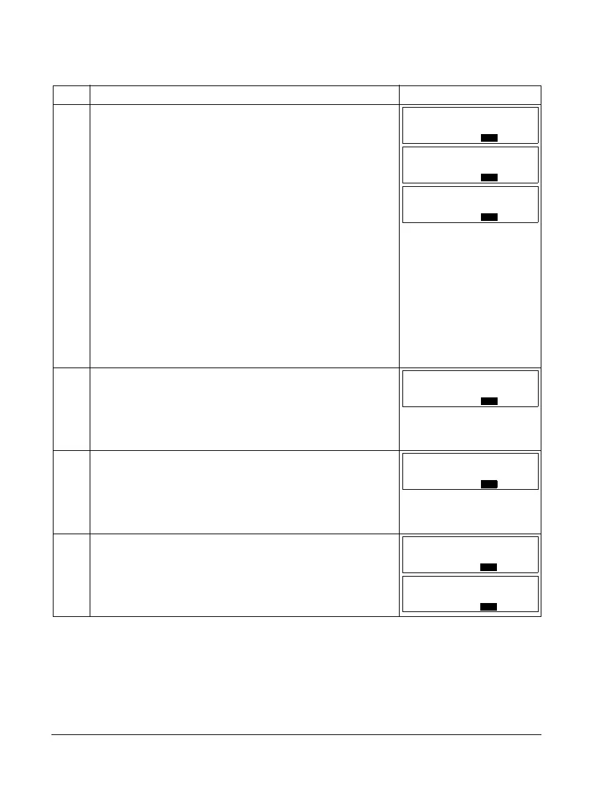
How to select the monitored signals
Step Action Display
1. You can select which signals are monitored in the Output mode and how
they are displayed with Group 34: PANEL DISPLAY parameters. See page
49 for detailed instructions on changing parameter values.
By default, you can monitor three signals by browsing (see page 65). The
particular default signals depend on the value of parameter 9902
APPLIC
MACRO: For macros whose default value of parameter 9904 MOTOR CTRL
MODE is 1 (VECTOR:SPEED), the default for signal 1 is 0102 SPEED, otherwise
0103
OUTPUT FREQ. The defaults for signals 2 and 3 are always 0104
CURRENT and 0105 TORQUE, respectively.
To change the default signals, select from Group 01: OPERATING DATA
up to three signals to be browsed.
Signal 1: Change the value of parameter 3401
SIGNAL1 PARAM to the index
of the signal parameter in Group 01: OPERATING DATA (= number of the
parameter without the leading zero), e.g. 105 means parameter 0105
TORQUE. Value 100 means that no signal is displayed.
Repeat for signals 2 (3408
SIGNAL2 PARAM) and 3 (3415 SIGNAL3 PARAM).
For example, if 3401 = 0 and 3415 = 0, browsing is disabled and only the
signal specified by 3408 appears in the display. If all three parameters are
set to 0, i.e. no signals are selected for monitoring, the panel displays text
“n.A”.
2. Specify the decimal point location, or use the decimal point location and
unit of the source signal [setting (9 (DIRECT)]. Bar graphs are not available
for Basic Operation Panel. For details, see parameter 3404.
Signal 1: parameter 3404
OUTPUT1 DSP FORM
Signal 2: parameter 3411 OUTPUT2 DSP FORM
Signal 3: parameter 3418 OUTPUT3 DSP FORM.
3. Select the units to be displayed for the signals. This has no effect if
parameter 3404/3411/3418 is set to 9 (DIRECT). For details, see
parameter 3405.
Signal 1: parameter 3405
OUTPUT1 UNIT
Signal 2: parameter 3412 OUTPUT2 UNIT
Signal 3: parameter 3419 OUTPUT3 UNIT.
4. Select the scalings for the signals by specifying the minimum and
maximum display values. This has no effect if parameter 3404/3411/3418 is
set to 9 (DIRECT). For details, see parameters 3406 and 3407.
Signal 1: parameters 3406
OUTPUT1 MIN and 3407 OUTPUT1 MAX
Signal 2: parameters 3413 OUTPUT2 MIN and 3414 OUTPUT2 MAX
Signal 3: parameters 3420 OUTPUT3 MIN and 3421 OUTPUT3 MAX.
LOC
PAR SET FWD
103
LOC
PAR SET FWD
104
LOC
PAR SET FWD
105
LOC
PAR SET FWD
9
LOC
PAR SET FWD
3
LOC
Hz
PAR SET FWD
00
.
LOC
Hz
PAR SET FWD
5000
.