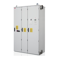
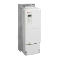
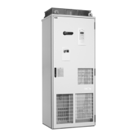
Inverter module cubicle from
front, door closed
Inverter module cubicle from
front, door open
Lower part of the inverter module cubicle from front,
shroud removed
2
3
5
6
4
4
Terminals are
behind the fan.
Grommet (in
IP54 units only)
a
b
b> 1/5 × a
Alternative 1:
360° grounding of the shield
Conductive gasket
360° grounding of the cable shield
at the inverter end
Alternative cable shield grounding means at the
motor end
Alternative 2:
grounding the twisted
shield
9

 Loading...


