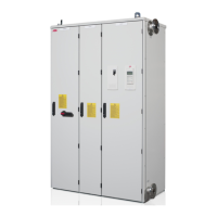
No. Description
A Incoming cubicle
B LCL filter cubicle
C Supply and inverter module cubicle
1 Drive control panel
2 Operating switch
3 Meters (optional)
4 Main switch handle
5 PE terminal (cabinet grounding busbar at the side
of the cabinet)
6 Auxiliary voltage transformer (T10)
7 Input power cable connection terminals
8 Main switch
9 Input fuses
10 Cabinet fan
11 LCL filter
12 IGBT supply module (behind the swing-out
frame)
13 Inverter module (behind the swing-out frame)
14 Swing-out frame with supply and inverter unit
control electronics, I/O terminal blocks and
communication options. See Swing-out frame
layout on page 33.
15 Cooling fans
16 Motor cable connection terminals (busbars
behind the fan)
17 Motor grounding terminal (common cabinet
grounding busbar behind the coolant pipe)
Doors closed
Doors open
1
8
7
5
4
A B C
2
3
12
10
11
6
13
16
15
15
17
14
9

 Loading...


