Hardware description
39
Layout of inverter module cubicle (frame 3×R8i)
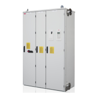
3×R8i inverter units are installed in a 700 mm wide cubicle as shown below.
No. Description
1 Inverter unit control panel
2 Inverter unit LED panel (optional)
3 Handle with marine construction (option +C121)
4 DC fuses
5 Inverter modules (behind the swing-out frame)
6 Swing-out frame with inverter unit control electronics, I/O terminal blocks and communication
options
7 Motor cable terminals (busbies behind the fans)
8 Terminal block for connection of prevention of unexpected start circuit (option +Q950)
9 Motor grounding terminal (common cabinet grounding busby behind the coolant pipe)
10 Fans
11 Terminal block for connection of motor temperature supervision (option +L505 or +L506)
3×R8i, door closed
12
3
9
3×R8i, door open
4
5
6
7
11
8
10

 Loading...


