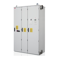
Door closed
Door open
600 mm wide cubicle
No. Description
1 Operating switch of the supply unit (Off/
On/Start)
2 Emergency stop reset push button (option
+G331)
3 Handle of grounding switch (option +F259)
4 Meters (options +G335, +3G335, +G334)
5 Main switch disconnector (air circuit
breaker)
6 Charging circuit switch and handle
7 Busbars for input power cables
8 PE main busbar of the cabinet (behind the
cooling liquid pipe)
9 Heat exchanger and fans
10 Grounding switch (option +F259)
4
6
5
9
10
8
7
3
12

 Loading...


