330 Parameters
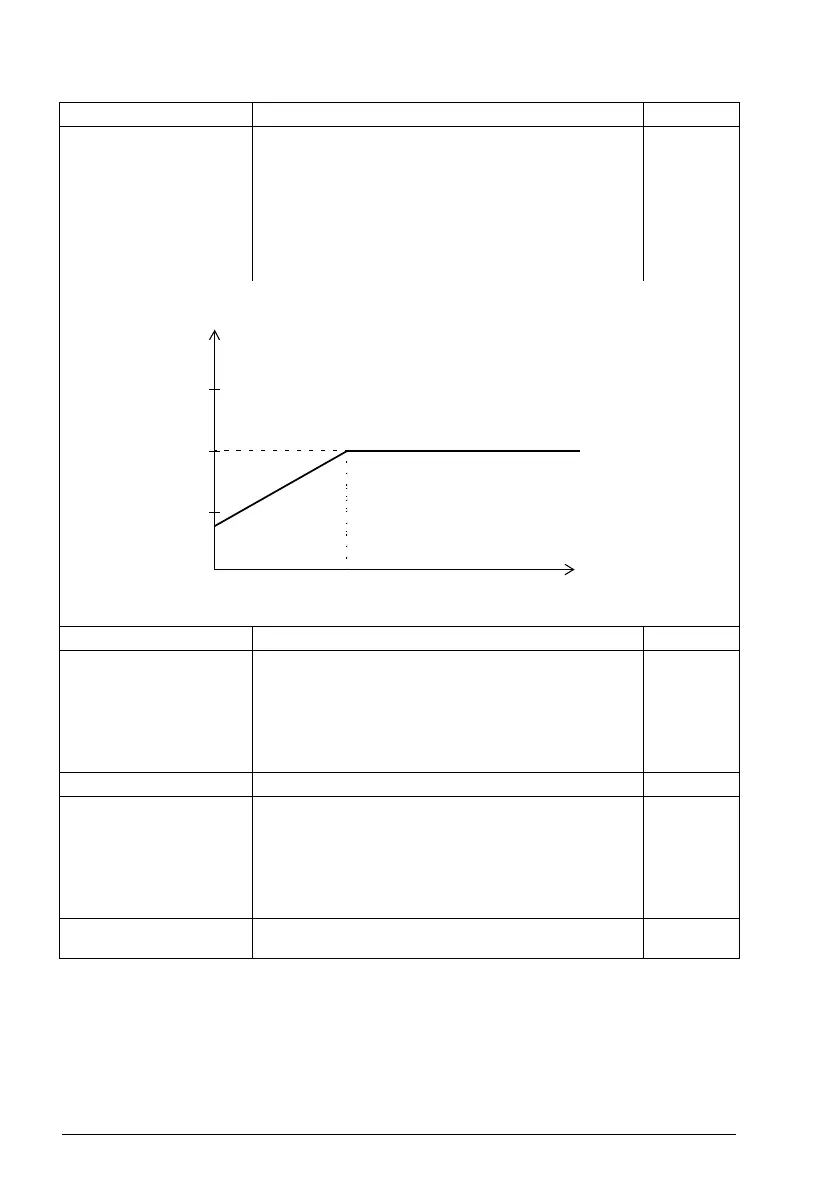
35.51 Motor load curve Defines the motor load curve together with parameters 35.52
Zero speed load and 35.53 Break point. The load curve is
used by the motor thermal protection model to estimate the
motor temperature.
When the parameter is set to 100%, the maximum load is
taken as the value of parameter 99.06 Motor nominal current
(higher loads heat up the motor). The load curve level should
be adjusted if the ambient temperature differs from the
nominal value set in 35.50 Motor ambient temperature.
100%
50 … 150% Maximum load for the motor load curve. 1 = 1%
35.52 Zero speed load Defines the motor load curve together with parameters 35.51
Motor load curve and 35.53 Break point. Defines the
maximum motor load at zero speed of the load curve. A
higher value can be used if the motor has an external motor
fan to boost the cooling. See the motor manufacturer's
recommendations.
See parameter 35.51 Motor load curve.
100%
50 … 150% Zero speed load for the motor load curve. 1 = 1%
35.53 Break point Defines the motor load curve together with parameters 35.51
Motor load curve and 35.52 Zero speed load. Defines the
break point frequency of the load curve i.e. the point at which
the motor load curve begins to decrease from the value of
parameter 35.51 Motor load curve towards the value of
parameter 35.52 Zero speed load.
See parameter 35.51 Motor load curve.
45.00 Hz
1.00 … 500.00 Hz Break point for the motor load curve. See par.
46.02
No. Name/Value Description Def/FbEq16
50
100
150
35.51
35.53
35.52
I/I
N
(%)
I = Motor current
I
N
= Nominal motor current
Drive output
frequency

 Loading...


