Parameters 347
DIO1 Digital input/output DIO1 (11.02 DIO delayed status, bit 0). 10
DIO2 Digital input/output DIO2 (11.02 DIO delayed status, bit 1). 11
Other [bit] Source selection (see Terms and abbreviations on page 148). -
40.31 Set 1 deviation
inversion
Inverts the input of the process PID controller.
0 = Deviation not inverted (Deviation = Setpoint - Feedback)
1 = Deviation inverted (Deviation = Feedback - Setpoint)
See also section Sleep function for process PID control (page
104).
Not inverted
(Ref - Fbk)
Not inverted
(Ref - Fbk)
0. 0
Inverted (Fbk - Ref) 1. 1
Other [bit] Source selection (see Terms and abbreviations on page 148). -
40.32 Set 1 gain Defines the gain for the process PID controller. See
parameter 40.33 Set 1 integration time.
1.00
0.10 … 100.00 Gain for PID controller. 100 = 1
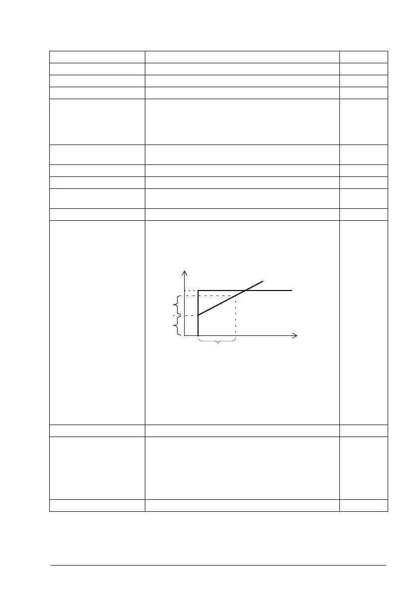
40.33 Set 1 integration
time
Defines the integration time for the process PID controller.
This time needs to be set to the same order of magnitude as
the reaction time of the process being controlled, otherwise
instability will result.
Note: Setting this value to 0 disables the “I” part, turning the
PID controller into a PD controller.
60.0 s
0.0 … 32767.0 s Integration time. 1 = 1 s
40.34 Set 1 derivation
time
Defines the derivation time of the process PID controller. The
derivative component at the controller output is calculated on
basis of two consecutive error values (E
K-1
and E
K
) according
to the following formula:
PID DERIV TIME × (E
K
- E
K-1
)/T
S
, in which
T
S
= 2 ms sample time
E = Error = Process reference - process feedback.
0.000 s
0.000 … 10.000 s Derivation time. 1000 = 1 s
No. Name/Value Description Def/FbEq16
Ti
O
I
G × I
G × I
I = controller input (error)
O = controller output
G = gain
Ti = integration time
Time
Error/Controller output

 Loading...


