Program features 71
To indicate faults in the followers, each follower must be configured to transmit its
status word as one of the above-mentioned data words. In the master, the
corresponding target parameter must be set to Follower SW. The action to be taken
when a follower is faulted is selected by 60.17 Follower fault action. External events
(see parameter group 31 Fault functions) can be used to indicate the status of other
bits of the status word.
Block diagrams of the master/follower communication are presented on pages 660
and 661.
Construction of the master/follower link
The master/follower link is formed by connecting the drives together using either
• shielded twisted-pair cable between the XD2D terminals of the drives*, or
• fiber optic cables. Drives with a ZCU control unit require an additional FDCO
DDCS communication module; drives with a BCU control unit require an RDCO
module.
*This connection cannot co-exist, and is not to be confused with, drive-to-drive (D2D)
communication implemented by application programming (detailed in Drive application
programming manual (IEC 61131-3), 3AUA0000127808 [English]).
Connection examples are shown below. Note that a star configuration using fiber
optic cables requires an NDBU-95C DDCS branching unit.
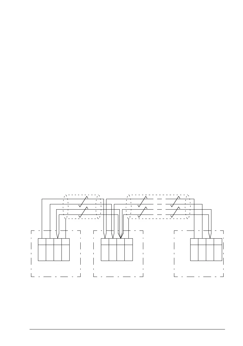
Master/follower wiring with electrical cable
Master
Termination ON
1
2
3
4
1
2
3
4
1
2
3
4
XD2D
B
XD2D
XD2D
A
BGND
Shield
B
A
BGND
Shield
B
A
BGND
Shield
Follower 1
Termination OFF
Follower n
Termination ON
See the hardware manual of the drive for wiring and termination details.

 Loading...


