NoteAction
xx2200000994
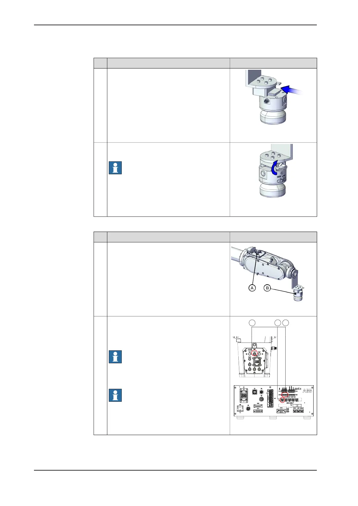
Insert the lead-through device to the base.2
xx2200000995
Turn the adjusting knob to lock the lead-through
device.
Note
Do not use excessive force!
The arrow in the figure indicates the direction of
locking the lead-through device.
3
Connecting the cables
NoteAction
xx2200000996
Connect the cabling between the lead-through
device and robot.
• R2.C2 connector on process hub of robot
(A)
• Lead through device connector (B)
1
xx2200000989
Connect the cable between robot and controller.
• R1.C2 connector on robot base (A)
• Ethernet switch port on controller (B)
• X19 connector on controller (C)
Note
Ethernet switch port is available for use only when
the 5 Port Ethernet switch option is selected.
Otherwise, connect the cable to the MGMT port.
Note
Pins 3 and 4 of X19 connector are used for the
lead-through device connection while pins 1 and
2 are occupied by the CP/CS cable for lamp unit.
2
Continues on next page
86 Product manual - CRB 1300
3HAC083111-001 Revision: B
© Copyright 2022-2023 ABB. All rights reserved.
3 Installation and commissioning
3.3.7 Installation of lead-through device
Continued
 Loading...


