Configuration 321
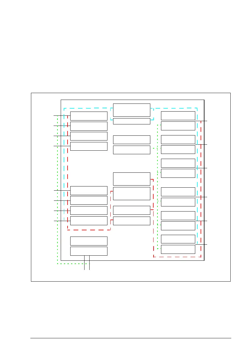
Example: The figure below shows an example I/O set-up:
• All inputs use diagnostic pulses with 1 ms width and 30 s period.
• One redundant cascaded connection from input 1 to output 7
• One safety relay (always redundant) connected to output 8 with feedback
connected to input 3
• All outputs, except X114:9, have active low logic state and diagnostic pulsing on.
Pulse width 1 ms and period 59 s.
• Output X114:9 has active high logic state and diagnostics pulses are not used.
Note: The safety relay inputs and outputs must be configured so that in the Safe state
the circuit is disconnected (0 V).
TP Diagnostic (test) pulses
X113:1
X113:2
X113:3
X113:4
I
N
P
U
T
S
O
U
T
P
U
T
S
X114:1
X114:2
X114:3
X114:4
X113:7
X113:8
X113:9
X114:7
X114:8
X114:9
X114:10X113:10
Safety relay 2
feedback = None
Cascade A =
X113:1 & X114:1 ->
X113:7 & X114:7
Safety relay 1
output = DO X113:8
& X114:8
Safety relay 1
feedback =
DI X113:4
DO diagnostic pulse
period = 59000 ms
DO diagnostic pulse
length = 1 ms
Safety relay 2
output = None
Cascade B = None
DI X113:1 diag
pulse on/off = On
DI X113:2 diag
pulse on/off = On
DI X113:3 diag
pulse on/off = On
DI X113:4 diag
pulse on/off = On
DI X114:1 diag
pulse on/off = On
DI X114:2 diag
pulse on/off = On
DI X114:3 diag
pulse on/off = On
DI X114:4 diag
pulse on/off = On
DI diagnostic pulse
length= 1 ms
DI diagnostic pulse
period = 30000 ms
DO X114:7 diag
pulse on/off = On
DO X114:8 logic
state = Active low
DO X114:8 diag
pulse on/off = On
DO X114:9 logic
state= Active high
DO X114:9 diag
pulse on/off = Off
DO X114:7 logic
state = Active low
DO X113:7 logic
state= Active low
DO X113:7 diag
pulse on/off = On
DO X113:8 logic
state = Active low
DO X113:8 diag
pulse on/off = On
DO X113:9 logic
state = Active low
DO X113:9 diag
pulse on/off = On