USER MANUAL | ICOS | INSTRUCTIONS | UM/ICOS-EN REV. B.2
3. Cap the Internal Pump Exhaust port with the provided ¼” Swagelok cap.
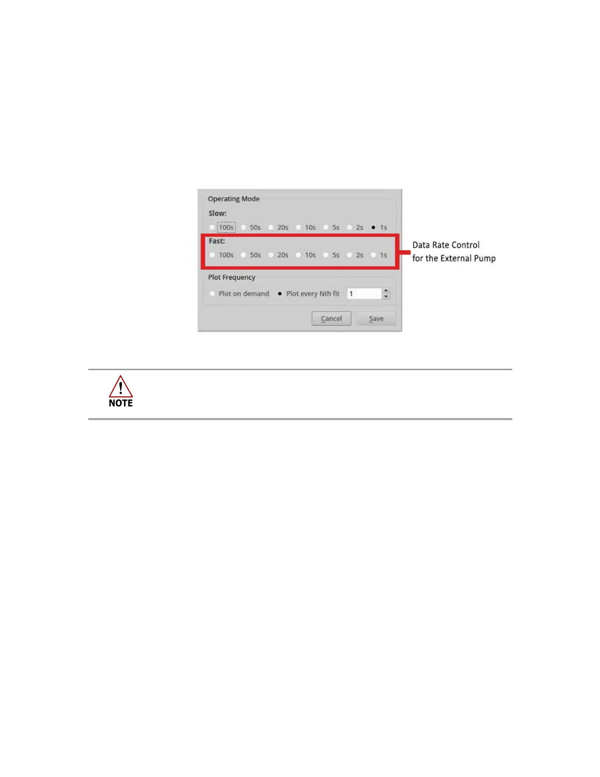
4. Click theRate button (clock icon) on the
User Interface Control Bar
(Figure 102) to
access the
Data Rate Control Adjustment Panel
. (Figure 103)
5. Click the Operating Mode radio buttons in the
FAST
row to select the rate at which
data is acquired. Click Save.
a. The Internal Pump will shut OFF, and the External Pump will power ON.
i. Fast = External Pump on/ Internal Pump off
ii. Slow = External Pump off/ Internal Pump on
Figure 103: Data Rate Control Adjustment Panel
The analyzer restarts sampling at whatever rate was set last.
6. To begin adjustments to the external throttle valve, turn the valve clockwise until it
is completely closed.
a. The gas flow will be routed through the electronic pressure controller.
b. The pressure controller is fully open but not able to pass sufficient flow to
the cell at its target pressure.
7. Turn the throttle valve counter-clockwise to open, while watching the Gas Pressure
reading in the
Parameter Window
of the
User Interface Control Bar
. (Figure 102)
a. Find the midpoint control range by slowly opening and closing the high flow
throttle valve while observing the reported cell pressure and noting the
points at which the control range begins and ends.
i. Each analyzer has a unique pressure set point. For example, if the
cell pressure is 140 Torr in slow mode, then the pressure reading
should be 140 Torr in high flow mode as well.
ii. The gas pressure is reduced to the point that it is within the
electronic pressure controller’s range. The ideal setting for the high
flow throttle valve is the middle of the electronic pressure
controller’s range.
b. Set the valve position to the middle of this range.
i. This control range typically spans approximately ½ turn of the high
flow throttle valve.

 Loading...


