145
ABOV Semiconductor Co., Ltd.
11.8.6 10-bit Timer 4 PWM Mode
The timer 4 has a high speed PWM (Pulse Width Modulation) function. In PWM mode, the 6-channel pins output up to
10-bit resolution PWM output. This pin should be configured as a PWM output by set PWM4E to ‘1’. When the value of
2-bit +T4CNT and T4PPRH/L are identical in timer 4, a period match signal is generated and the interrupt of timer 4
occurs. In 10-bit PWM mode, A, B, C, bottom(underflow) match signal are generated when the 10-bit counter value
are identical to the value of T4xDRH/L. The period of the PWM output is determined by the T4PPRH/L (PWM period
register), T4xDRH/L (each channel PWM duty register).
PWM Period= [T4PPRH/T4PPRL ] X Source Clock
PWM Duty(A-ch) = [ T4ADRH/T4ADRL ] X Source Clock
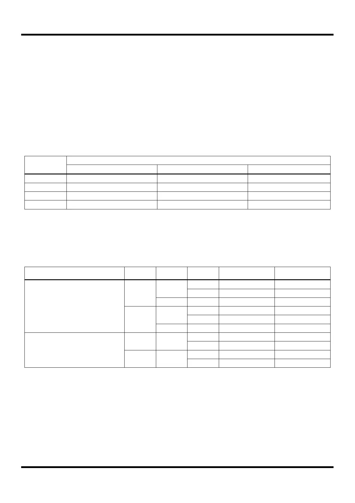
Table 11.12 PWM Frequency vs. Resolution at 8MHz
The POLxA bit of T4PCR3 register decides the polarity of duty cycle. If the duty value is set same to the period value, the
PWM output is determined by the bit POLxA (1: High, 0: Low). And if the duty value is set to "00H", the PWM output is
determined by the bit POLxA (1: Low, 0: High).
Table 11.13 PWM Channel Polarity
 Loading...


