EasyManuals Logo

Abov MC96F6432S Series User Manual

Abov MC96F6432S Series
283 pages
To Next Page IconTo Next Page
To Previous Page IconTo Previous Page
Page #29 background imageLoading...
Page #29 background image
29
MC96F6432S
ABOV Semiconductor Co., Ltd.
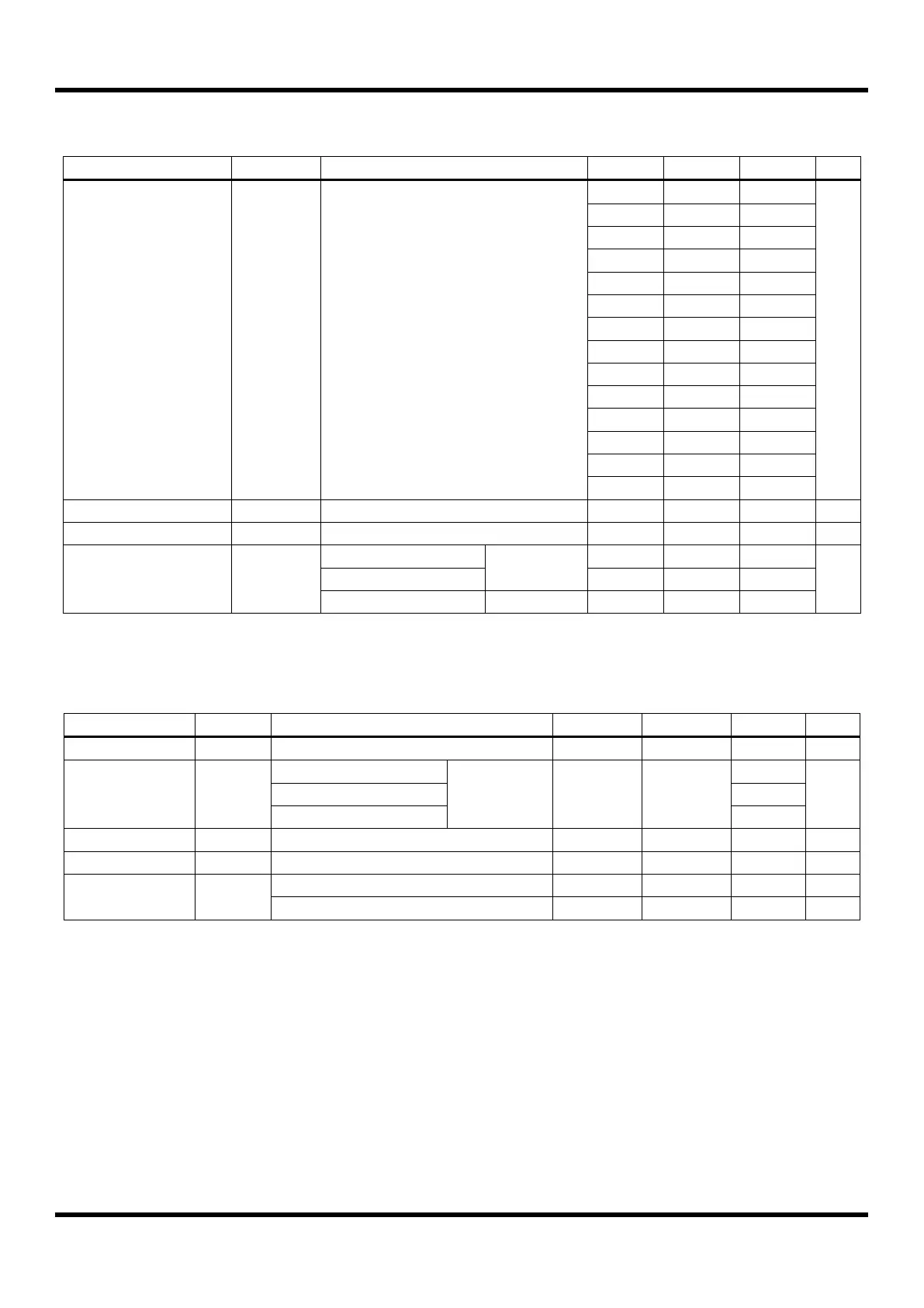
7.5 Low Voltage Reset and Low Voltage Indicator Characteristics
(T
A
=-40°C ~ +85°C, VDD=1.8V ~ 5.5V, VSS=0V)
Parameter
Symbol
Conditions
MIN
TYP
MAX
Unit
Detection Level
V
LVR
V
LVI
The LVR can select all levels but LVI
can select other levels except 1.60V
–
1.60
1.79
V
1.85
2.00
2.15
1.95
2.10
2.25
2.05
2.20
2.35
2.17
2.32
2.47
2.29
2.44
2.59
2.39
2.59
2.79
2.55
2.75
2.95
2.73
2.93
3.13
2.94
3.14
3.34
3.18
3.38
3.58
3.37
3.67
3.97
3.70
4.00
4.30
4.10
4.40
4.70
Hysteresis
â–³V
–
–
50
150
mV
Minimum Pulse Width
t
LW
–
100
–
–
us
LVR and LVI Current
I
BL
Enable (Both)
VDD= 3V,
RUN Mode
–
14.0
24.0
uA
Enable (One of two)
–
10.0
18.0
Disable (Both)
VDD= 3V
–
–
0.1
Table 7.5 LVR and LVI Characteristics
7.6 High Internal RC Oscillator Characteristics
(T
A
=-40°C ~ +85°C, VDD=1.8V ~ 5.5V, VSS=0V)
Parameter
Symbol
Conditions
MIN
TYP
MAX
Unit
Frequency
f
IRC
V
DD
= 2.0 – 5.5V
–
16
–
MHz
Tolerance
–
T
A
= 0°C to +50°C
With 0.1uF
Bypass
capacitor
–
–
±1.5
%
T
A
= -20°C to +85°C
±2.5
T
A
= -40°C to +85°C
±3.5
Clock Duty Ratio
TOD
–
40
50
60
%
Stabilization Time
T
HFS
–
–
–
100
us
IRC Current
I
IRC
Enable
–
0.2
–
mA
Disable
–
–
0.1
uA
Table 7.6 High Internal RC Oscillator Characteristics
NOTE)
1. A 0.1uF bypass capacitor should be connected to VDD and VSS.

Table of Contents

Questions and Answers:

Question and Answer IconNeed help?

Do you have a question about the Abov MC96F6432S Series and is the answer not in the manual?

Abov MC96F6432S Series Specifications

General IconGeneral
BrandAbov
ModelMC96F6432S Series
CategoryMicrocontrollers
LanguageEnglish

Related product manuals