89
ABOV Semiconductor Co., Ltd.
10.11 Interrupt Timing
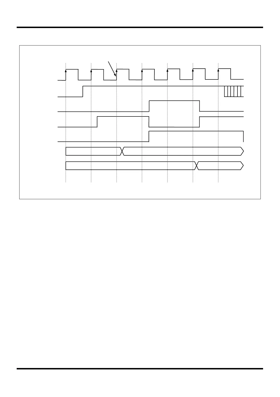
Figure 10.10 Timing Chart of Interrupt Acceptance and Interrupt Return Instruction
Interrupt sources are sampled at the last cycle of a command. If an interrupt source is detected the lower 8-bit of
interrupt vector (INT_VEC) is decided. M8051W core makes interrupt acknowledge at the first cycle of a command,
and executes long call to jump to interrupt service routine.
NOTE)
1. command cycle CLPx: L=Last cycle, 1=1
st
cycle or 1
st
phase, 2=2
nd
cycle or 2
nd
phase
10.12 Interrupt Register Overview
10.12.1 Interrupt Enable Register (IE, IE1, IE2, IE3)
Interrupt enable register consists of global interrupt control bit (EA) and peripheral interrupt control bits.Total 24
peripherals are able to control interrupt.
10.12.2 Interrupt Priority Register (IP, IP1)
The 24 interrupts are divided into 6 groups which haveeach 4 interrupt sources. A group can be assigned 4 levels
interrupt priority using interrupt priority register. Level 3 is the highest priority, while level 0 is the lowest priority. After a
reset IP and IP1 are cleared to ‘00H’. If interrupts have the same priority level, lower number interrupt is served first.

 Loading...


