EasyManua.ls Logo

Abov MC96F6432S Series User Manual

Abov MC96F6432S Series
283 pages
To Next Page IconTo Next Page
To Previous Page IconTo Previous Page
Page #234 background imageLoading...
Page #234 background image
234
MC96F6432S
ABOV Semiconductor Co., Ltd.
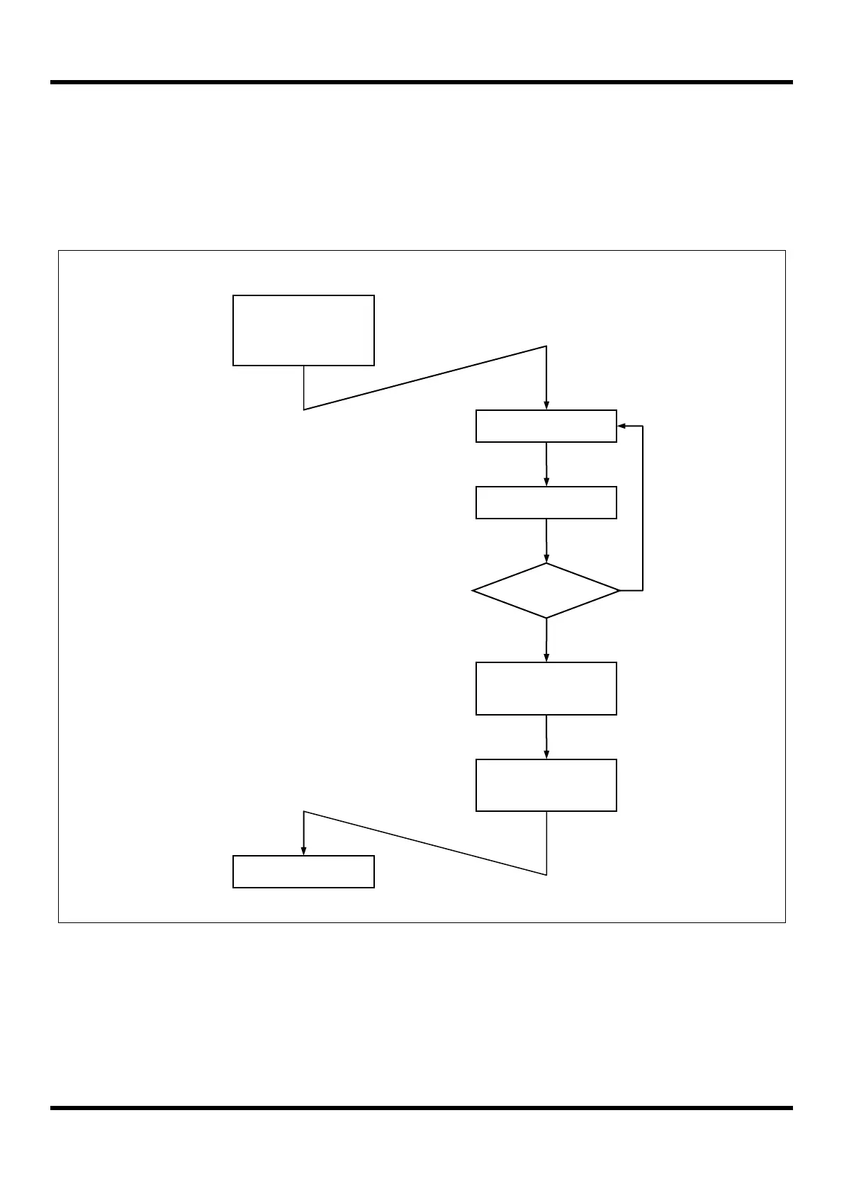
12.5 Release Operation of STOP Mode
After STOP mode is released, the operation begins according to content of related interrupt register just before STOP
mode start (Figure 12.3).If the global interrupt Enable Flag (IE.EA)is set to `1`, the STOP mode isreleased by the
interrupt which each interrupt enable flag = `1` and the CPU jumps to the relevant interrupt service routine. Even if the
IE.EA bit is cleared to 0, the STOP mode is released by the interrupt of which the interrupt enable flag is set to 1.
Figure 12.3 STOP Mode Release Flow
SET PCON[7:0]
SET IEx.b
STOP Mode
IEx.b==1 ?
Interrupt Request
STOP Mode Release
Y
Interrupt Service
Routine
Next Instruction
N
Corresponding Interrupt
Enable Bit(IE, IE1, IE2, IE3)

Table of Contents

Question and Answer IconNeed help?

Do you have a question about the Abov MC96F6432S Series and is the answer not in the manual?

Abov MC96F6432S Series Specifications

General IconGeneral
Core8051
Flash Memory64KB
PWM Channels6
Communication InterfacesUART, SPI, I2C
Operating Frequency24 MHz
ADC Channels8
ADC Resolution10-bit
SPI1
I2C1
PackageLQFP48
Operating Voltage2.4V to 5.5V
Operating Temperature-40°C to 85°C

Related product manuals